
Menu:
Version:
June 14, 2010:
Revised: v2.0
ZL2PD CMOS HF Digital Dial
A frequency counter built from five or six CMOS ICs which can be used to display the operating frequency of a transceiver, transmitter or receiver. Two versions are described; One with a really basic resistor-capacitor timing reference, and the other with a more conventional crystal timebase.
The design was originally published in 'Break-In', New Zealand's amateur radio magazine in May/June 2009, and is republished here with the permission of the editor.
Note: 'Break-In' is a term used in amateur
radio to describe a system which allows another person's signal to be
heard in the brief intervals between transmitted Morse Code symbols.
Introduction
The key objective of my Christmas-New Year project in 2008, a small homebrew QRP 80m SSB transceiver, was to keep the transceiver as cheap and simple as possible. It used several handfuls of BC548 transistors, and it’s been lots of fun to build. The transceiver’s VFO used one of those ‘polyvaricon’ plastic variable capacitors found in many budget AM/FM radios. Once I got the VFO tuning over the right range, and fairly stable, the next step was to build some sort of simple matching frequency display so I could see the transceiver's operating frequency. The basic design came from John, VK3AJG, and can be found here.At first, I looked at building a basic mechanical dial. Most of these seemed to require lots of space on the front panel, as well as considerable mechanical skill and material. A ‘slide-rule’ dial arrangement spread across the horizontal width of the front panel was about as good as I could manage, but the dial cord got in the way of other controls, and it was not particularly reliable.
I could determine my frequency to within about 5 kHz, but it was far from one of those perfectly linear readouts that commercial transceivers feature. Sadly, I don’t have the mechanical acumen (or tools) to build something as clever as the Heathkit or HRO dials of old. Even if I did, these dials can have errors of this order of magnitude from end to end anyway.
No, what I wanted was a simple compact display with, ideally, 1kHz accuracy. Since I know the band I'm using the transceiver on (80m, in my case), my digital dial need only display the three ‘kHz’ digits of my operating frequency to provide adequate information and resolution.
Design Options
With
these basic requirements decided, I could have built one of any number
of existing microprocessor-based frequency counter designs. Several of
my own counter designs use LED displays, and one or two use LCD
displays of various sorts, too. Most designs seen in magazines and on
the web appear to favour the use of larger alphanumeric LCD displays. I
have one example of a multi-digit 80MHz LED readout frequency counter
here on my website and I recently published a design for another
portable counter using just a single LED display in a recent ‘Break-In’
article (Reference 1 - All references are found at
the bottom of this page). That's also shown on this website.But unless you can purchase a kit of parts for one of these microprocessor-based counters, or unless you can find a design for which pre-programmed microprocessors are available, or unless you have access to suitable facilities, then getting hold of all of the bits and pieces necessary for building both the counter, as well as the items necessary to actually program the chips, can make building these counter a major challenge.
If you want a digital dial, rather than just a basic frequency counter, then many of these designs require some sort of software change. With the exception of direct conversion and some software based radios, the VFO frequency of any receiver, transmitter or transceiver is actually offset by the IF frequency. For example, if a transmitter is operating on a transmit frequency of 3.70 MHz and an IF of 9 MHz, then the VFO to be either on 12.7 MHz or 5.3 MHz. To correctly display the operating frequency from a measurement of the VFO frequency, the software may need to be modified to remove MHz digits from the display, say, or changed to add or subtract the IF frequency from the measured VFO frequency.
While many people have the skills necessary to make those sorts of changes to software, there are probably more who have very little idea where to begin. The learning curve on some of the software required to program microprocessors can also be fairly steep.
One such microprocessor-based digital dial which does not require software changes was published recently in Break-In. (Reference 2) However, the programmer and software described on the associated website for this unit requires some specialised expertise in Linux operating systems.
The design shown here on this webpage seeks to address some of those issues. It is arguably the simplest possible design for a digital dial. It uses as few as five standard CMOS chips. With the exception of the first divider chip, it is not necessary to use ‘HC’ type higher speed CMOS chips. Using ‘HC’ chips will allow measurement of VFO frequencies on almost all HF equipment.
This article actually describes two versions of the digital dial. The first version features a ultra-basic resistor/capacitor clock reference for the digital dial, and uses five chips. The second version uses a slightly more expensive ceramic resonator or crystal reference oscillator to give better performance, but at the cost of an additional sixth standard CMOS chip. No microprocessors were harmed in the construction of this dial!
While the resistor/capacitor version appears basic, don’t be too quick to spurn the possibilities. It’s certainly nowhere near the accuracy of the crystal version, and you wouldn’t want to rely on it for operating close to band edges. But having built this version, in part to establish its practicality, it turned out to be as accurate as the analog dials on some quite well known commercial HF transceivers. Specifically, it can be adjusted to the required frequency and remain accurate to within 2 kHz at constant room temperatures, and within 5 kHz over temperature shifts of up to 10C from ambient room temperatures.
There are two important limitations of this design. Firstly, it assumes the VFO frequency tracks the operating frequency. For example, my BC548 transistor transceiver uses a VFO which tunes from 9.5 to 9.9 MHz and a 6 MHz IF when operating on the 3.5 to 3.9 MHz 80m band. This allows the kHz value of the VFO frequency to be displayed in order to show the operating frequency. For operation on 3.665 MHz, say, the digital dial circuit will measure 9.665 MHz. The circuit ignores the MHz information, and displays ‘665’. I could use the same dial design with a 20m transceiver tuning 14.0 to 14.5 MHz, for example, with a 9 MHz IF and a VFO tuning from 4.0 to 4.5 MHz.
Secondly, the design assumes the use of ‘integer’ IF frequencies i.e. 5 MHz, 9 MHz, etc. An IF of 8.625 MHz, for example, won’t allow this design to be used. Allowing for such increased flexibility would require doubling the number of chips in the digital dial, although such designs exist for those interested. (One useful design may be found from Reference 3, described in Polish)
My design provides no such elegant flexibility. Simple, cheap and basic are the key words here.
Circuit Description
The
digital dial circuit is shown in Figure 1. It consists of three
sections: The input divider (IC5), the decade counters (IC2, 3 and 4),
and the reference frequency source (IC1). A 74HC4060 CMOS divider is used as the input stage, dividing the input frequency by 16. Other devices could also be used, along with changes to the PCB layout, such as a 74HC4040 or 74HC4020, or even a 74LS196 chip, in that case with a further change in the reference oscillator. I used a 74HC4060 simply because I had some in my parts bins.

Figure 1. Circuit diagram of the RC reference version of the digital dial
The divided input frequency is passed to the three CD4026 decade counters which, in turn, directly drive three 7-segment LED common cathode displays. The LED displays do not require any buffer resistors. The 4026 chips count for a time period set by the ‘logic low’ half-cycle of the square wave output of IC1, a CD4069 hex inverter reference oscillator. The other half-cycle of the 4069 oscillator halts the count to allow the display to be read. The 4026 counters are then reset by a positive-going pulse generated by C5, R1 and D1.
The reference frequency required is determined by the display resolution and the input division ratio. In theory, the reference frequency should be 31.25 Hz (32mS cycle time) but the time taken to reset the decade counters increases the time required slightly, and the reference frequency required for kHz resolution is just less than 30 Hz. The cycle time is actually 33.5mS.
The 4069 oscillator uses standard metal film resistors and a MKT or mylar capacitor to minimize temperature drift. A multi-turn pot is used to set the reference frequency. The PCB allows for up to two fixed resistors as well as the multi-turn preset, all in series, to ease the task of setting the correct frequency. I found 25 turn presets at one of my local suppliers (Jaycar), but standard 10 turn pots will work too. Also, due to the tolerance of the capacitor (C1), R1 may need to be changed for either a 47k or a 33k in some cases.
A second version of the reference oscillator is illustrated in Figure 2. This uses a ceramic resonator of 500 kHz. 500 kHz ceramic resonators can be found in some consumer infrared remote controls although most seem to use 455 kHz resonators. The advantage of this type of oscillator is its much enhanced stability. It does make the dial slightly more expensive to build.

Figure 2. Circuit diagram of the enhanced reference oscillator for the digital dial
Dial accuracy can be maintained to less than 1 kHz under almost all circumstances. If this version is used, omit IC1, R1, R2, RV1 and C1 from the digital dial PCB and connect the outputs of this reference oscillator directly to pins 6 and 8 of the now vacant IC1 location on the PCB.
A variety of crystals can also be used instead of the 500 kHz ceramic resonator with a few other minor changes. Details on the identification of suitable crystals and the configuration of the two-chip programmable reference oscillator are the subject of another page on my website. You can find those details here.
Construction
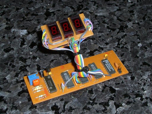
The PCB
layout for the RC clock version is shown in Figure 3, and the component
layout in Figure 4. It measures 100mm x 35mm, dimensions which match
the other boards developed for my latest homebrew SSB transceiver. In
use, it draws about 30mA, almost all consumed by the LED displays. Note
that the LED displays are mounted on a separate PCB and connected via a
wiring loom of 22 wires. 
Figure 3. PCB layout - RC reference version

Figure 4. Component layout - RC reference version
The display board layout I used is not shown here because I’ve found there is next to no standardisation in LED display pinouts over the years. Your 7-segment displays are unlikely to match mine. The easiest way to build the display section is to use a scrap of veroboard to mount your displays. Then simply wire across to the main digital dial PCB.
Alignment and Operation
Once
it’s built, align the oscillator variable resistor to give about 30 Hz
on pin 6 of IC1. Connect the digital dial to your VFO. This VFO
requires at least 2Vpp of input signal, and some VFOs may require a
buffer amplifier be used between the VFO output and the input to the
digital dial. One buffer that’s worked well for me is shown in Figure
5. 
Figure 5. A simple input buffer amplifier
Once set up, either tune the VFO to a known frequency, or connect another frequency counter to the VFO. Simply fine tune RV1 until the digital dial displays the correct frequency. This sounds easy, but it’s equally easy to hit on a nearby setting that gives an apparently correct result. Tune the VFO to another frequency, say the opposite end of the band, just to check you have aligned RV1 correctly.
Over a two week test period, my RC-reference digital dial was able to display the VFO frequency in my transceiver within 2kHz. At turn-on on one cool morning, with the digital dial circuit board lying open on my bench, the dial result was 4 kHz off, but it gradually came within 1 kHz after about 10 minutes. Must have needed the digital equivalent of a morning coffee.
If this level of performance in your digital dial is not acceptable, then by all means use the alternative oscillator circuit. It’s slightly more expensive to build, but it will resolve this issue completely. It’s over to you.
See you on 80m!
References
1.
“Single Digit Frequency Counter, ZL2PD, Break-In, May/June 2008, page
15-162. “A Digital Frequency Display”, VK3BHR, Break-In, March/April 2006, page 14-15
3. See http://www.elportal.pl/pdf/k15/36_01c.pdf
Downloads
Click here here to download the PCB layout
Click here to download the PCB component placement details
Want to go back to the main page? Click here to return directly.