
Menu:
Version:
Dec 09, 2015:
Revised: v1.2
The Saga of the Soldering Stations
 Designing
and building a temperature controller for a soldering iron might seem
unusual in these days of cheap Chinese-made soldering stations. In my
case, I went even further, designing three different controllers.
Crazy? Well, here's
the full story.
Designing
and building a temperature controller for a soldering iron might seem
unusual in these days of cheap Chinese-made soldering stations. In my
case, I went even further, designing three different controllers.
Crazy? Well, here's
the full story.
Introduction
For over thirty years, I used a Weller temperature controlled soldering station. When I bought it, it was very expensive, and I gave it a lot of thought before finally buying it. The years of use I had from that soldering iron certainly proved it to have been a wise choice.When the element in the iron finally expired, I naturally purchased a new element. It was surprisingly expensive. Actually, I could have purchased at least two new Chinese-made soldering stations for the price of that element, but I was a happy Weller user, right?
Well, that element barely lasted six months. Fortunately, I was able to obtain a replacement under warrantee, but the replacement didn’t seem to give the same performance as the original part. I had become used to the original iron’s high power output and fast heating, and that new element just wasn’t doing that.
These original Weller soldering stations control the tip temperature through the “Curie Effect”. A magnet in the tip loses its magnetism at a specific temperature, say 700F. This controls a magnetic switch powering the iron. In turn, that controls the tip temperature. It's surprisingly accurate.
While working in the Pacific Islands, I came across a temperature controlled iron from a small Japanese company, Hakko. The major Japanese consumer electronics company we represented recommended these original Hakko 900 soldering irons for equipment repair. It used an electronic temperature control system. It was very effective, and they were excellent value for money. But I never bought one at the time because I already had my reliable Weller.
Faced with this under-performing Weller at about the time I moved to the Middle East, I thought I’d just buy a cheap temperature controlled soldering iron to take with me. Something temporary. It looked a bit like the one shown here.
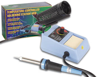
Oh, big mistake. Huge! The temperature control on that cheap soldering iron was utterly pathetic. Opening it up, I found a basic light dimmer inside without any temperature feedback mechanism at all. That piece of rubbish got tossed in the junk box where it belonged.
Shortly afterwards, while travelling, I found a reasonably priced temperature controlled iron in a Radio Shack store. Chinese made, it used a cheap copy of the original Hakko handpiece along with a microcontroller for temperature control. The LCD display showed the current and user-set temperatures. It even had three memories. Feature rich! It worked reasonably well, although it was much less powerful than my Weller, and nowhere near as quick to heat up.
One problem I noticed after six months of use was that it seemed to chew through the tips quickly. On a subsequent trip to the UK, I purchased several sets of cheap clone tips via a well known website. These tips worked just fine. But while I was browsing the various websites to buy those tips, I noticed that a number of the same Chinese companies also offered clone copies of the original Hakko 907 24V/50W handpiece at minimal cost. On a whim, I purchased one of those as well. I figured it might be useful as a spare.
Sometime after this, during one of my weekends, I was glancing though my odds and ends, searching for some part or other, and I stumbled across that spare handpiece. It started me thinking. I could rip out the awful guts of that cheap dimmer-based iron that still sat in the corner of my junk box. Maybe I could use some of the parts such as its simple base and stand along with that spare Chinese Hakko 907 handpiece and, with a second-hand 24VDC laptop power supply from my junkbox, perhaps I could build a simple controller and get a complete temperature controlled soldering iron out of this collection of stuff.
Turns out, yes, I could. But along the way, I ended up designing not one, but three different controllers. Go figure.
Controller #1 – The Analog Version
I
began this "design and build" saga with a glance around the Internet to
see what others have done. It boiled down to a relatively small
collection of circuits ranging from light dimmers (No!), several direct
copies of the original Hakko analog controller circuit, and several
very elegant and surprisingly complex microprocessor designs. These
complex designs however permitted the use of a wide variety of
handpieces including the popular Hakko 907 type as well as those using
different sensors and elements. They can even use the latest
(fabulously expensive) Weller iron handpieces, or at least their clones
made in the depths of China.|
Sensors and Soldering Irons
There are two basic sensor types used to measure temperature in soldering irons; Thermistors or thermocouples. Thermistors are positive temperature coefficient (PTC) resistors. Resistance increases as temperature rises. Thermocouples are made by welding two dissimilar alloys together. They generate a tiny voltage which increases linearly with temperature. The original Hakko irons, such as the 907, use thermistors. Some other brands, and some later Hakko irons use thermocouples. Either can do the task quite adequately. The thermal lag and therefore measurement accuracy is arguably in favour of thermocouples, but these can be more difficult to use in a controller. The Hakko 907 clone handpieces use thermistors, and these circuits all assume their use. |
I decided to build an simple existing analog design. I found a recent design in EDN magazine (September 8 2013) which used a single quad op-amp and power FET. However, as I worked my way through the design, I could see a number of problems.
The design certainly worked, but some components served no purpose. Others could get very hot in use. Meanwhile, some parts of the circuit seemed to be a little unusual. And expensive 1% tolerance components were apparently required for some parts, but for no apparent reason. The basic concept however looked fine to me, so I quickly redesigned it from end to end to give me a design that would actually function much better.
And here is my version. (Right click on the image to see it full size)
Circuit Description
The
Hakko 907 handpiece has a soldering tip heated by a ceramic
encapsulated heater element. This is powered from 24VDC. The heater
element also contains a positive thermal coefficient (PTC) thermistor
whose resistance increases with increasing temperature. It typically
ranges from 40 ohms at room temperature to about 140 ohms at 450C. This
allows the temperature of the iron to be measured remotely. Since the
thermistor sensor is not located precisely at the end of the tip where
the soldering is done, the temperature control of the
iron’s tip cannot be perfectly accurate. However, given the close
proximity of the thermistor to the tip, it’s proven to be quite
adequate in practice. (Note: Other types of soldering irons are different and may not work with these circuits!)This controller measures the thermistor’s resistance using a balanced resistor bridge comprising the Hakko thermistor (TH1), R6, R7, VR1 and R8. VR1 sets the desired soldering iron temperature. When the correct temperature is reached, the voltage at the top of the thermistor TH1 on J2/4 is equal to the voltage at the top of VR1.
Opamp IC2a is arranged as a balanced differential amplifier to measure the voltage difference across the two arms of the bridge. If the iron’s temperature is less than the temperature set by VR1, the output of the opamp will be high. If it is at the correct temperature or above, the opamp’s output is low.
The voltage driving this bridge comes from a low frequency square wave oscillator (IC1a) running at about 1 Hz. The 50% duty cycle output is buffered by Q1 to reduce the load on the opamp. Since the voltage driving the bridge is turning on and off at 1 Hz, set by the values of R4 and C1, the resulting output of the difference amplifier (IC2a) will also be a square wave, either of high amplitude if the iron is below the set temperature, or nearly zero if at or above the set temperature.
The blue LED (D1) on the output of the difference amplifier clearly shows this, flashing brightly if the iron’s temperature is too low, and dimming or extinguishing if the temperature is reached or exceeded.
This output is converted into a variable amplitude sawtooth by IC2b, C2, D2, D3 and associated parts. This is fed to a non-inverting Schmitt trigger which switches at about 6V. It has about 0.5V of hysteresis. The resulting output is a constant high level at power-on when the iron is cold or heating up, or low when the set temperature is reached. As the iron heats up and cools down by a few degrees during use, this stage outputs something like a pulse-width modulated square wave to maintain the set temperature. The switching voltage output changes very quickly, and it’s fast enough to avoid any heating of the DC switch, Q2.
Q2 is rated for switching up to 100V and 16A but the device’s gate voltage, VGS, is limited to 20V. Since I planned to use 24V for the soldering iron, this same supply powers the opamp. That results in an output voltage (22V or so, typically) which exceeds the device limits. The resistive divider (R18 and R19) resolves this issue, limiting the maximum input voltage to about 12V.
The green LED (D4) shows when the iron is up to temperature. When the iron is below the desired temperature, the blue LED (D1) flashes brightly, and this green LED will be either off or very dim, since Q2 will be turned completely on to heat up the iron’s element. Once the temperature is reached, Q2 turns off, and the green LED (D4) can receive the full 24V rail via the heater element, and it’ll be at full brightness.
Q2 does not need a heatsink because it operates either on or off. When turned on, the FET’s channel resistance is about 0.05 ohms, and the dissipated power under full load (2 - 3A depending on the iron’s element) is less than 1/4W. The case temperature of the IRF540 will rise 15 degrees or so while the iron is heating up, and then cool down rapidly to room temperature as soon as the iron is at the required temperature. Despite running an iron handpiece at over 3A, I never found the FET became even warm, and it’s operating well within its ratings.
Finally, if you look closely at the circuit diagram, you may see what looks like a stray 1M resistor (R23). This resistor ties the metal tip of the iron handpiece to ground for static protection. This makes it safe to use with CMOS parts, for example.
Construction and Testing
I built
this unit on a piece of perforated board, and it worked perfectly from
the outset. The really nice thing about it was that no special parts
were required. All of the resistors can be standard 5% 1/4W or 1/2W
parts, although all capacitors must be rated for 50V or 63VDC. Be
careful not to use the more common 16V rated parts for, say, C1 or you
will get a surprise when it fails abruptly. 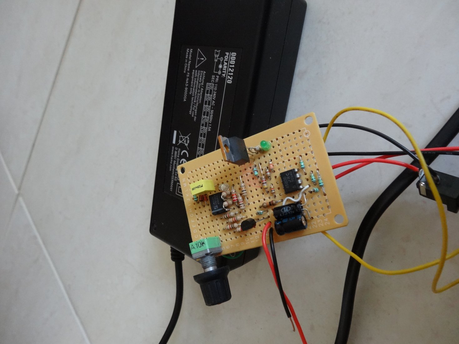 I
used two LM358 dual op amps rather than a single LM324 simply because I
had those on hand. Either approach is fine, but I think using the two
LM358 op amps ended up being the better option given the relatively
large number of discrete parts required.
I
used two LM358 dual op amps rather than a single LM324 simply because I
had those on hand. Either approach is fine, but I think using the two
LM358 op amps ended up being the better option given the relatively
large number of discrete parts required.The blue LED doesn’t extinguish completely, but tends to flash less brightly once the iron is up to temperature. The green light will come on briefly when power is first applied, perhaps for about a second or so while C1 initially charges, and then it will remain off until the set temperature is reached. Then, depending on the thermal lag in the iron, the required set temperature and the air temperature, it will either only pulse on briefly from time to time, or pulse more regularly as heat is applied to the iron to maintain the temperature.
Typical laptop power supplies produce about 19V, but running the Hakko-type 24V irons at that voltage is not ideal. It reduces the nominal power of the iron from a useful 50W to a less than desirable 30W. Fortunately, I had a redundant universal laptop power supply I bought on a trip some years ago which allows the output voltage to be set from 16V to as much as 24V. This was perfect for this requirement, and it works extremely well. My handpiece had a low resistance element and drew just over 3A from the power supply, but it handled that load with ease, as did the controller FET (Q2).
In use, the iron works really well, reaching its operating temperature in about 10 seconds. While not as fast as the latest $800 commercial soldering stations which heat up their tiny iron elements in less than 4 seconds, this analog controller works surprisingly well.
Dissatisfaction and the New Design
Even
while I was building this first design, I could see that the design was
going to require a lot of parts. Sure, they are all cheap and readily
available, but still…And then there were those LED indicators. They were useful, but the blue LED did not turn off completely when the set temperature was reached. I could have added a zener in series to sort that out, but I didn’t have any temperature readout either, aside from the panel markings on VR1.
I could have added an analog voltmeter onto TP1 to provide a temperature display. I've included those details on the schematic above for those wanting to try out this design. It can provide a direct readout of the current iron temperature, and some basic commercial soldering stations do something very similar. But meters are expensive, and that added still more parts to the design. In any case, I didn't have a suitable meter.
Perhaps an LCD display would be a good idea, I thought. That led me to the first of two further designs.
Controller #2 – Microcontroller Version with LCD
The
idea behind this next design was to reduce the number of parts to a
more reasonable number while also providing more information to the
user. Other microcontroller-based soldering station designs which have LCDs appear to have gone all-out to offer a wealth of additional features and flexibility, especially the commercial models. Some offer USB memory features to store programming profiles and operating temperatures. There are some that even have LAN interfaces and touch-sensitive LCD control panels. Many allow user control adjustments to be locked out, clearly useful on production lines. Automatic configuration of a handpiece.... The feature list that some stations have is almost endless.
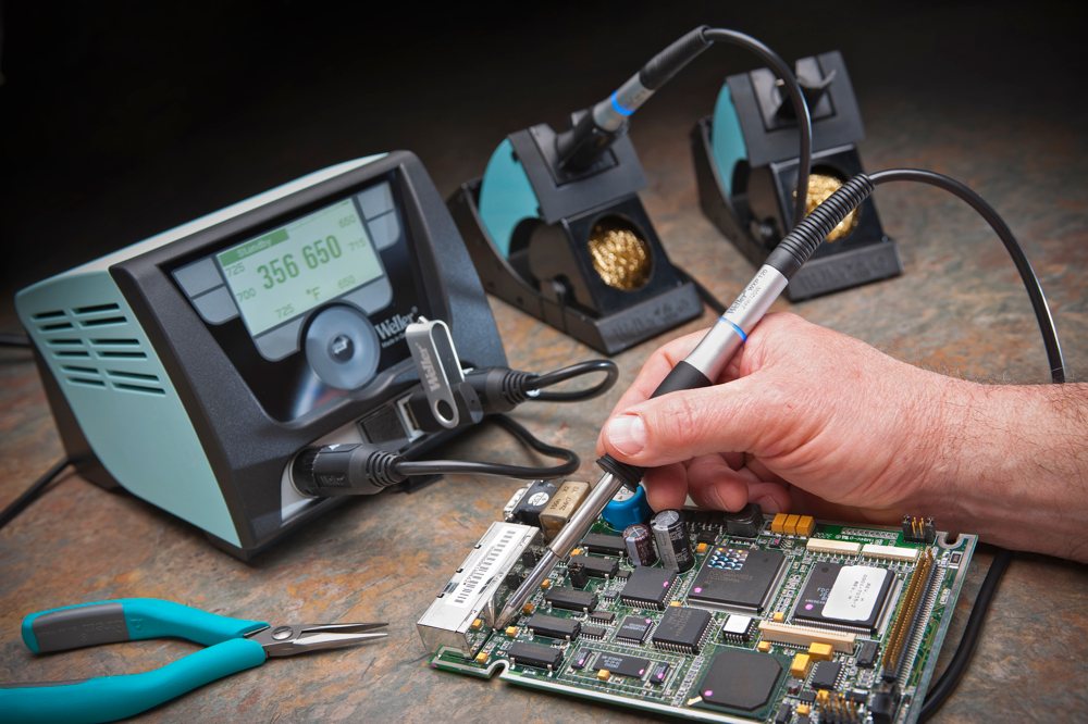
One such "top of the line" soldering station can be seen in the picture to the right. It also allows several soldering handpieces to be connected to the soldering station base. Although it's got a number of great features and it's probably very nice to use, that's not a soldering station I could ever afford to buy for just my hobby.
When you come right down to it, all that most users really need in a soldering station is the ability to control the temperature of a typical soldering iron. In my case, that soldering iron was a standard clone Hakko 907 handpiece.
Actually, there are a few other 'nice to have' features. The soldering iron itself should be reasonably light and easy to hold. The tip should be no larger than the tip of a pencil, and able to be swapped out for different shapes including a tiny 1mm tip and larger 3mm tip. Finally, the cable between the iron and the controller or soldering station base should be as light as possible, and very flexible. It needs to be about 1m long, and made from heat-resistant material to avoid damage if it momentarily comes into contact with the soldering iron. Finally, the iron tip should be static-grounded to ensure safe use with sensitive CMOS components.
The Hakko 907 clone handpiece I had in my spares bin met almost all of these goals. I would have liked a slightly lighter cable, but at the price, I had no complaints. The remaining features looked perfectly achievable, although adding an LCD display meant I had to use a microprocessor for the controller. The LCD could display both the user-set temperature and the current operating temperature of the iron at the same time. I could add a “memory” pushbutton switch to allow a preset temperature to be selected. That feature seemed to be popular on several soldering stations. Not sure I could see the point of it, but since I was going for the “feature-rich” design, maybe I could add it.
I decided to try to use the smallest and probably cheapest microcontroller in my collection, the 8-pin ATtiny85. It’s possible to use larger devices, such as the 28-pin or 40-pin ATmega chips, but that just seemed unnecessary to me, at least at first glance. Several commercial designs use such devices, as does a readily available Chinese-made controller you can buy online for these Hakko-compatible handpieces. It uses an ATmega328 to drive a three digit LED display in a remarkably similar fashion to a design developed in Russia several years ago.
Several other designs use Arduino boards, some even using two 28-pin microcontrollers as well as a further processor on a secondary display board. The list goes on.
Well, all of these designs probably work very well, but I was aiming at something with fewer parts than my analog design. But could I use an 8-pin ATtiny for a soldering station with an LCD? Surely there are insufficient pins, I hear you claim.
Well, it turns out to be perfectly feasible, thanks to the increased availability of serial LCDs. Fortunately, these LCDs are no more expensive than standard alphanumeric LCDs either. And here's the schematic. (Again, right click on that schematic below if you want to see it full size)

Circuit Description
The Midas-branded serial LCD I used is available from Rapid Electronics in the UK, and
similar
displays are available from other suppliers via the internet. It’s a
compact LCD, and reasonably easy to use. It only needs two processor
pins to drive it using the industry-standard I2C serial protocol. The
only other connections required are for the power supply. This can be
either 3.3V or 5V depending on requirements. I’ve successfully used
these displays with both voltages with excellent results.The two-line display shows the set temperature (top line) as well as the current temperature (lower line) as measured from the soldering iron handpiece. For simplicity, temperature is set by adjusting the variable resistor VR1. This allows the iron to be adjusted from about 50C to 450C (100F to 850F).
The thermistor resistance is determined by measuring the voltage from a voltage divider comprising a 100 ohm resistor (R2) and the thermistor. This is operated from 5V in common with the rest of the controller to ease interface issues. An adequate output voltage range is produced by the iron’s thermistor under these conditions to avoid the need for further amplifier or buffer stages, although this is discussed further below.
For this arrangement to work properly, it’s important to ensure that the thermistor wiring goes directly to the processor. The wiring from the heater element should go as directly as possible to the power supply. This ensures noise from the element heating and cooling does not affect the thermistor voltage measurement.
Construction and Testing
Again,
this circuit was built on another scrap of prototyping board, but,
honestly, it hardly lasted a day on my bench. It didn't even last long
enough for me to take a photo of it. Completely forgot, actually.You see, having built it and started to test it, I quickly realized that the LCD was largely unnecessary. Sure, the temperature details were all there on the screen for me to see, but after an hour or so, I realised I was using it just like my current RadioShack soldering station. On that station, I just set the required temperature once and then simply use the soldering iron. I hardly ever varied the temperature setting, and I didn't make any further use of the display after that.
If that was the case with this new design, it brought the rest of the design back under the microscope. If there was really little need for an LCD display, what was the absolute minimum that was necessary in a good soldering iron controller?
And that led very quickly me on to…
Controller #3 – Microcontroller Version with LEDs
I began
this new version by removed the LCD from the previous design, and
returning to the simplicity of a pair of indicator LEDs.Yes, I'd come full circle. This would have a red LED to
indicate when the iron was heating up, and a green LED to show when the
iron was at the correct operating temperature. I would not even have to
look at the LEDs directly to see what my soldering iron was doing.
These LEDs can be seen out of the corner of my eye while I'm focused on
soldering the PCB.Since I have never (ever!) needed to set my iron’s temperature to an accuracy of 1, 5 or even 10C (Does anyone?), I realized that a simple analog potentiometer was perfectly adequate to set the required temperature within reasonable margins. Assuming an adjustment range of, say, 150 – 450C (300 – 850F) which seemed to cover the most useful range of temperatures I use, the setting resolution is probably about +/- 10C which seemed more than adequate. Actually, after I did some initial work on some of the behind-the-scenes maths to do with the software, I gave the analog adjustment a slightly greater range by setting the ultimate control limits of the potentiometer at 100C and 500C. That still gave me the ability to set a temperature within about +/-10C, at least in theory.
Counting everything up, this approach left me with one pin free on my little processor chip. After some careful thought about what was useful and necessary, I added a pushbutton switch to select a 'standby' mode. This would switch the iron to a low temperature when not being used, say while you get a cup of coffee or drill a couple of holes in a PCB.
Mechanical Design
Have
you noticed? Most soldering stations are pretty boring affairs. Almost
without exception, they consist of a basic box with a few indicators
and a variable control of some sort. Some have that LCD to jazz up the
design a bit. Occasionally, the designers will really get carried away
and add a blue LED or paint the metal box in a bright colour. All
fairly unimaginative.I could see that my third design was going to be compact. With the power supply contained in a separate laptop supply tucked away under the bench, I was free to consider a range of design options for the enclosure that might otherwise not be possible.
And then, why do some soldering stations take up so much space on the bench? Sure, some seem to need a lot of parts. Many (sensibly) use a very large and heavy transformer for the power supply. I didn't have those constraints, and the recent acquisition of a 3D printer and some excellent design software allowed me considerable freedom to examine the overall mechanical design.
In keeping with the idea of "minimalist design", I've tried to keep the overall dimensions fairly compact while also making it easy to use and, I think, quite nice to look at. Apart from the need to make sure the iron stayed well away from the plastic parts (which will melt at just 150C or so), it did result in one minor problem which I'll describe later.
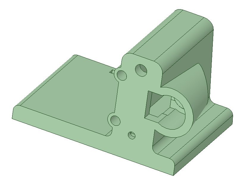
The enclosure design for the soldering station was created using DesignSpark Mechanical software
Circuit Description
This
controller uses the fewest possible number of parts yet it still
provides excellent control over temperature. It also provides a simple
set of indications for the user to show the status of the iron at any
time. (Right click on the schematic below to see it full size)
As mentioned earlier, two LEDs are used to indicate operation. Since I was powering this from a recycled 24V/3.5A laptop supply, thermal dissipation in the 5V regulator turned out to be a critical factor. If the 5V rail draws what might appear to be a fairly reasonable load current, even as little as 20mA from a 24V supply for example, the 5V regulator can get very hot very quickly. To avoid that problem, I had to absolutely minimize the 5V current drain. That began by using high efficiency LEDs. They are very (very!) bright with just 1mA of current flow.
As with the LCD version, the thermistor resistance is continuously measured using the ATtiny’s 10-bit analog to digital (A2D) converter. However, the simple resistor divider arrangement used in the previous design required too much current from the 5V rail. The alternative, running a similar resistor divider arrangement directly from the 24V rail, will result in some high power levels being dissipated in the series resistor. That approach simply wasn't going to work.
This design uses the soldering iron’s thermistor as the control resistance in a LM317LZ constant current generator. This device is a low current variable voltage regulator which comes in a compact TO-92 package. These are quite inexpensive. I could have used another LM317LZ as the main 5V regulator, and would do so if I was looking at making a few hundred of these soldering stations as kits for others to build, or if I was taking this design into full production in China. But I was just making one soldering station. I already had a handful of 78L05 regulators which use that same TO-92 package, and using one of these saved adding two more resistors to the parts count. That's why I stuck with the 78L05 for the 5V regulator.
Meanwhile, that LM317LZ constant current generator feeds R3, a 390 ohm resistor on pin 1 of the ATtiny. The 10 bit internal A2D converter in the ATtiny measures the voltage drop across R3 which, of course, is proportional to the thermistor resistance and the tip temperature. Aside from the tip of the soldering iron and the thermistor, nothing in the controller gets hot, and nothing other than standard 5% 1/4W resistors are required. The only unusual thing about the circuit here is that the voltage measured on pin 1 of the ATtiny is inversely proportional to the iron's temperature. As tip temperature rises, this voltage falls. This arrangement also provides a very useful voltage range for the range of temperatures being measured.
The required soldering iron temperature is set by the user's adjustment of variable resistor, VR1. It’s possible to use a rotary encoder here, but that results in some other problems. Firstly, there is no easy way to indicate temperature with a rotary encoder without using an LCD or a 7-segment LED display. Secondly, rotary encoders don’t all operate in the same way. Software either needs to handle all those variations or a specific encoder type has to be specified. By contrast, variable resistors are easy to buy, inexpensive, and they work just fine. Using a 10k linear variable resistor also kept the 5V current load down.
The "Standby" front panel switch is simply connected directly to a processor pin. There's an internal pullup resistor in the ATtiny which is set by software, saving another part. If this switch is pressed, the setting on VR1 is ignored by the controller. It assumes instead that the iron’s temperature should be 100C. It's an arbitrary value which is hard-coded in the software, but it seemed a good compromise between extending the tip's life and allowing a reasonbly swift return to the original user-selected temperature.
In this standby mode, the two LEDs alternately flash. Pressing the standby button again will return the iron to the user-set temperature on VR1, and the LED indicators also return to normal. This standby mode reduces possible tip damage which can result from leaving the soldering iron operating unused at high temperatures for long periods of time.
Finally, the ATtiny controls the 24V going to the iron’s element via FET (Q1) as in the previous two designs. The low on-resistance of the FET ensures that it dissipates very little power. In use, and without any heatsink, the device’s TO-220 package does get hot, but very briefly, perhaps only for five seconds. The iron then reaches operating temperature and the FET turns off, cooling rapidly. Maintaining the iron at any set temperature requires minimal power, and the FET remains cool while it does that.
As a result of this, I didn’t bother with a heatsink for Q1, and it’s been fine in practice. But if you are nervous, bolt on a small TO-220 heatsink and the part will never get more than warm, ever.
Construction and Testing
I built
my version initially on another scrap of prototyping board. It measured about
40mm x 20mm. I used some PCB pins to allow me to wire all the various
controls, LEDs and the iron wiring to the board. It was quite small. I used an ATtiny45 in the prototype because I had run out of ATtiny25 chips. I could also have used an ATtiny85. No changes to the software are required unless you are recompiling the source code. In that case, of course, you would have to set the appropriate processor device definition. The software, written in BASCOM (AVR Basic) takes up about 50% of the space in the ATtiny25, or 25% of the ATtiny45. The source code and HEX file are available for download below.
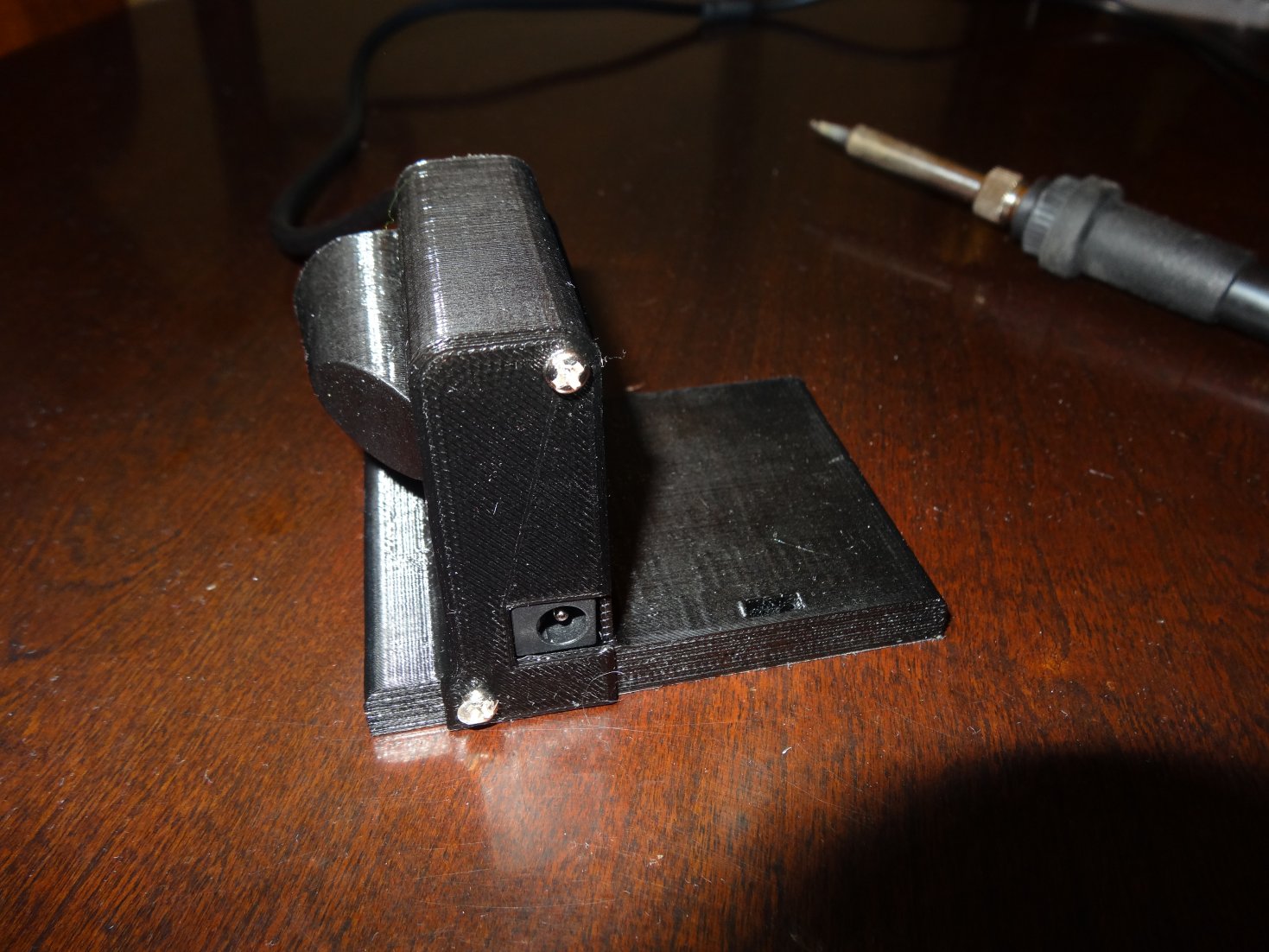
I designed the enclosure using DesignSpark Mechanical and built the enclosure using my 3D printer. I used standard 1.75mm PLA filament and 0.2mm layers. As you can see from the photographs, the enclosure is quite compact. A sub-panel is also required for the front panel to cover the potentiometer, and a back cover. Both are also printed from PLA filament. All of these STL files can be downloaded from the links below.
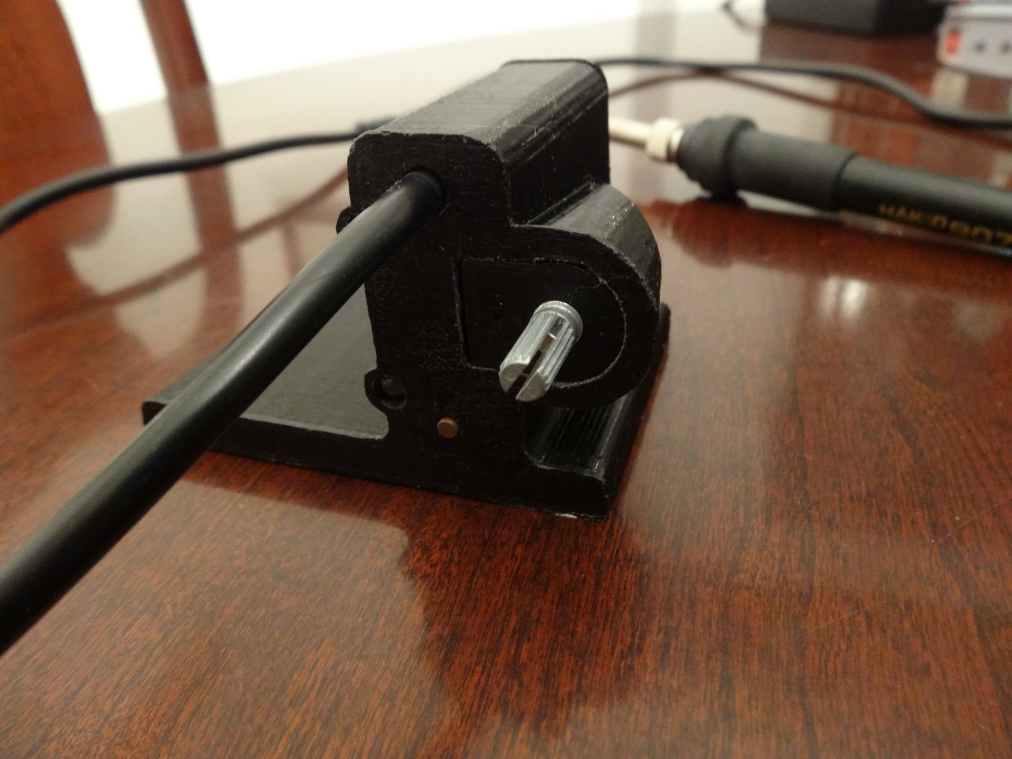
The soldering iron holder from that cheap and nasty "light dimmer" controlled soldering iron that ended up in my junk box was put to good use here. Suitable holders can also be fabricated from metal or thick wire. The one I recycled simply slots into the base of the 3D-printed controller base. To reduce the size of the soldering station base still further, and since I had no mating connector for the iron anyway, I wired the handpiece cable directly to the board through a hole in the front panel.
The LEDs fit into place from inside the enclosure, green at the top and red closest to the base. Wiring should be soldered to these prior to fitting into place. Switch SW1 should similarly be fitted with wires and pushed into place from the inside of the enclosure. I used a drop of hot-melt glue to hold it in place from the rear.
Potentiometer VR1 slides in from the front. This is a standard 10k linear potentiometer with a 16mm diameter body. The wiring should be soldered to the three pins of VR1 first, and the wires fed through the plastic base from the front into the cavity for the control board, and then the pot can be pushed into place.
A small cover is then pressed into place over the front of VR1 to give a flat finish to the front panel. It can be glued into place if necessary, but I found this unnecessary. There are two tiny holes in this sub-panel to allow it to be removed with a paper clip and repositioned, if necessary.
The control board slides into the enclosure vertically from the rear once the LEDs have been pushed into place. Another small sub-panel is screwed onto the back to protect the wiring and board. The DC socket is left exposed for connection to the laptop power supply.
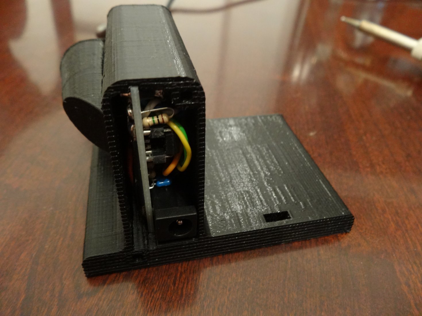
Rear view of soldering station showing cover screwed into place with small self-tapping screws
Finally, the panel artwork is glued onto the front panel of the enclosure. I printed the artwork on a colour laser printer, and covered it with transparent stick-on plastic film I bought from a stationary store before gluing it onto the enclosure.

Here is the front panel artwork which was created using CorelDraw.
The artwork is glued down everywhere except within a few mm of the switch icon. Pressing on that "down arrow" icon depresses the tactile switch which lies just below it. The button protrudes about 0.5mm from the surface of the front panel. It's hidden below the label and works very nicely.
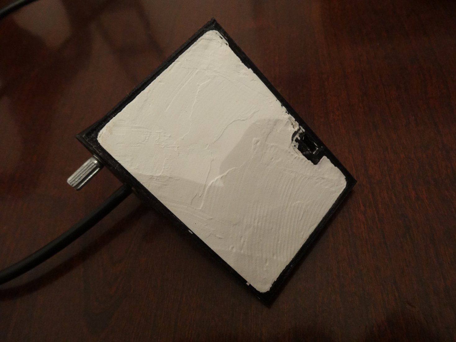
A challenge with using a 3D-printed PLA plastic base like this for a soldering iron, aside from the potential risk of melting the plastic if the iron gets too close to it, is that it has very little weight. When I put the soldering iron in its holder, the base was not stable.
I was expecting to see this and had allowed for it in the design. I copied a common practice used by a number of manufacturers, and I made the base of the unit hollow. Before mounting any of the parts, I filled this hollow base first with several layers of small lead balls (I used a small handful of shotgun pellets) and then poured in a layer of plaster of paris over them to hold everything in place. Then I left it to harden overnight. That definitely stops the base from falling over, and practically anchors it safely in place on my bench.
 I
know, I can hear the screams of outrage from some readers. But I am also aware
that there are some very expensive desk telephones out there, for
example, made by a number of well respected high end leading brands that
contain a large lump of plaster of paris hidden from view just like
this to do precisely the same task. And it works really well.
I
know, I can hear the screams of outrage from some readers. But I am also aware
that there are some very expensive desk telephones out there, for
example, made by a number of well respected high end leading brands that
contain a large lump of plaster of paris hidden from view just like
this to do precisely the same task. And it works really well.For those wanting a less ‘agricultural’ approach, feel free to prcision-mill a plate of thick aluminium or other metal to glue into that space instead.
PCB
After
several weeks of use, I decided this third design might be of interest
to others. To make it a little easier to copy this design, I produced a
tiny PCB. Since I was planning to travel to Europe a few weeks later, I
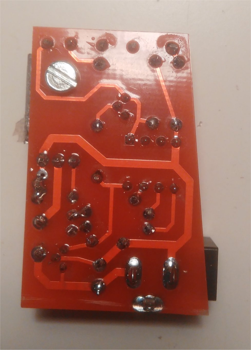
had the PCB made in China. You can see the blank PCB and the final
assembled unit in the pictures below. All of the required files are
available for download below. The component locations and connections
are clearly marked on the PCB. 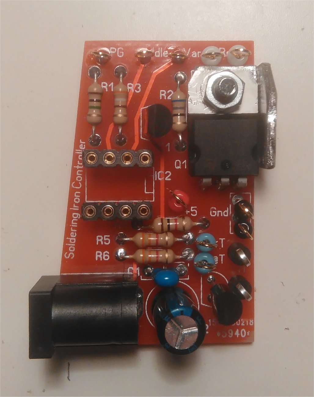
A small piece of aluminium was folded, drilled and added as a spacer between the FET and the PCB. It 's a very modest heatsink which I suspect is not doing much good, but given there's very little dissipation from that FET, it's robably doing no harm either. The tiny loops are used to connect the wiring to the PCB. They are not essential. Connections can be made directly to the PCB.
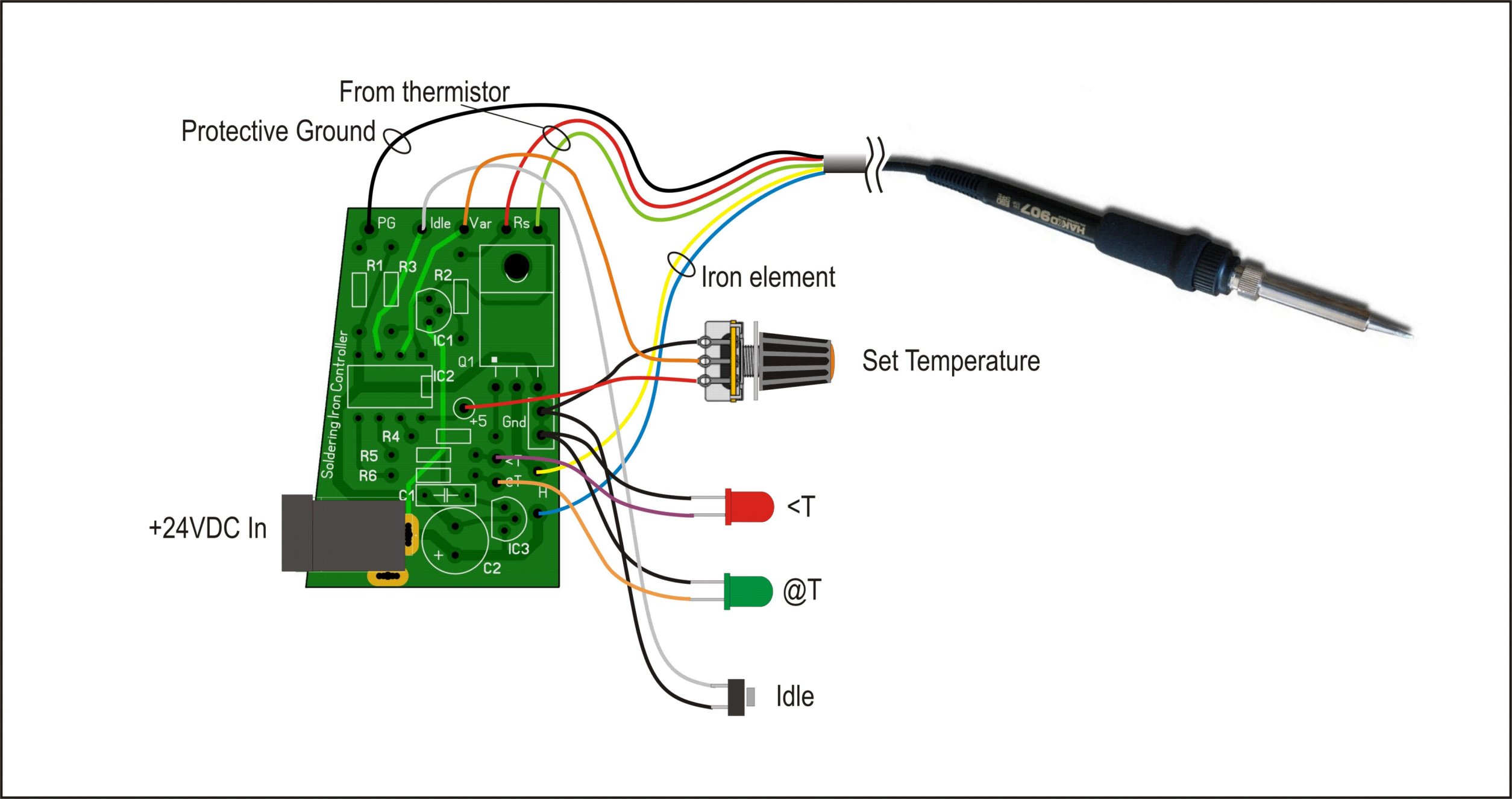
Once completed, with wiring attached, the PCB can be slid into place in the 3D printed enclosure. The wiring details are shown in the diagram below. (Right-click on the image as usual to see it in greater detail).
Note: The colours of the wires coming from the Hakko-clone iron may NOT be the same as those in my iron so you should check these carefully before connecting it up.
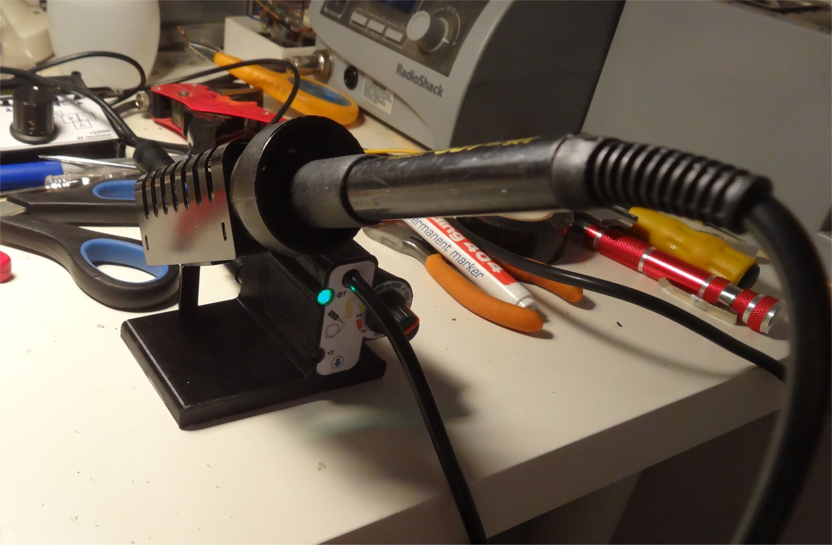
Results
My adventures with designing soldering iron controllers turned
out to be somewhat more involved than expected, but I'm really pleased with the final design. So much so, that I’ve moved the
old RadioShack soldering station off my bench permanently and replaced
it with Design #3. You can see the old soldering station just before it got moved, sitting in
the background in the picture below. It took up an acre of bench space, and it was heavy
(Almost 3kg). Also, the handpiece cable seemed to always flop into just
the wrong place while I was using it, so there were a lot of good reasons to consign it to a distant corner of my junk box.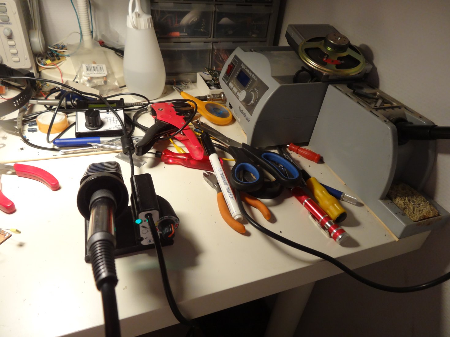
It just took me three tries to get there, I guess.
Other Recommendations
For
those that would prefer to avoid all of this process and just go out
and buy a soldering iron that works well for hobby or semi-professional
use, which is perfectly understandable, I can recommend the Hakko FX888. A number of the less expensive Chinese clones of the original Hakko 900-series soldering stations are also quite satisfactory. If you do decide to buy one of these less expensive soldering stations, then, when it arrives, you should take some time to take a very careful look at it, inside and out. Plan to tidy up any loose wiring, poor solder joints, or any mechanical issues like loose bolts (especially the critical earthing wiring) that seem to be a feature of some of these units.
Some other shots of Design #3:
The
board slides into the rear of the base. It's held vertically with slots
formed in the 3D-printed base. This photo shows the original prototype
board rather than the later PCB.
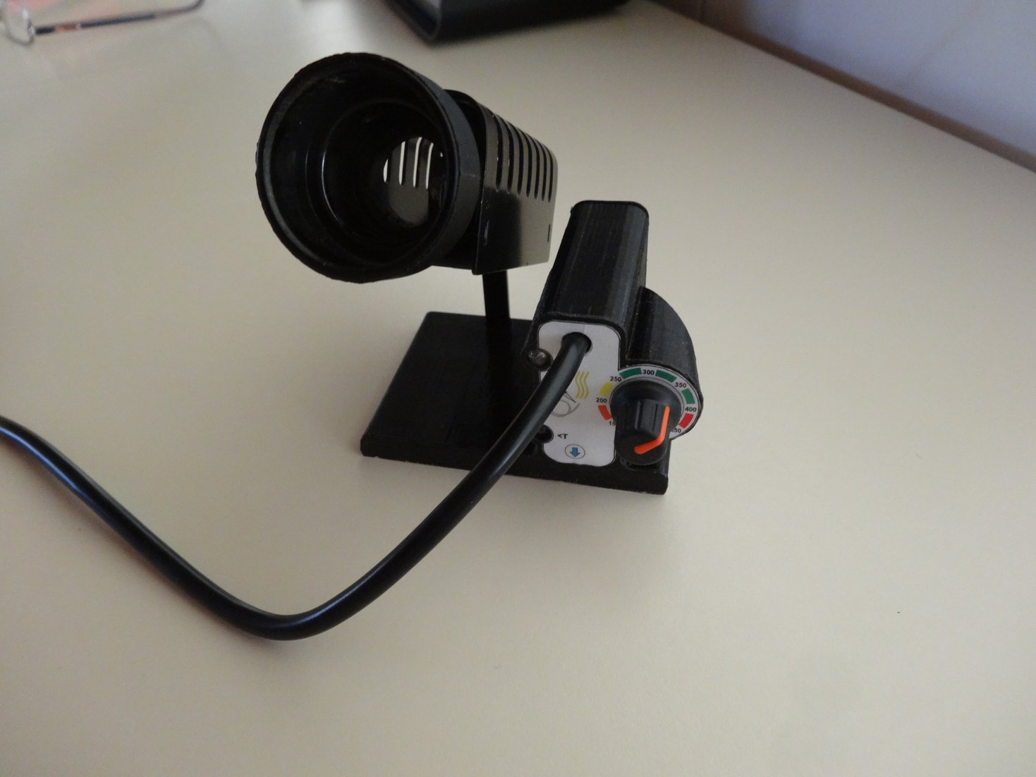
Soldering iron holder mounted in the base
Downloads
Software: This ZIP file contains the BASCOM source code and the compiled HEX file for Design #3(Fuses: HIGH: 05fh, Low: 062h, Lock: 0ffh, Extended: 0ffh Note: The chip's reset pin is used as an input)
Note: Fuse settings noted in the previous line were updated/corrected Dec 9th 2015 - Thanks go to Jerby for pointing out my error in transcribing the details from the Bascom software listing. Sorry!
Soldering station enclosure: This ZIP file contains the files required to 3D print the main enclosure, as well as the front and rear sub-panels (STL format)
Front panel artwork: Download this JPG file
PCB design: Download this ZIP file
Want to go back to the main page? Click here to return directly.