
Menu:
Version:
May 17, 2020:
Revised: v2.0
An AM/FM/CW Scanning RF Signal Generator
This is a low cost readily constructed RF signal generator with a wealth of features which was published in Silicon Chip magazine in June and July 2019 and reprinted in UK's Practical Electronics magazine in June and July 2020.
Some information has been added below about solutions to a couple of problems experienced by some builders

Introduction
This signal generator was the result of several years of patient development. Designed around the use of a readily available low cost AD9850 DDS module and controlled by an Atmel ATmega328 processor, it provides a variety of features ideal for a wide variety of applications.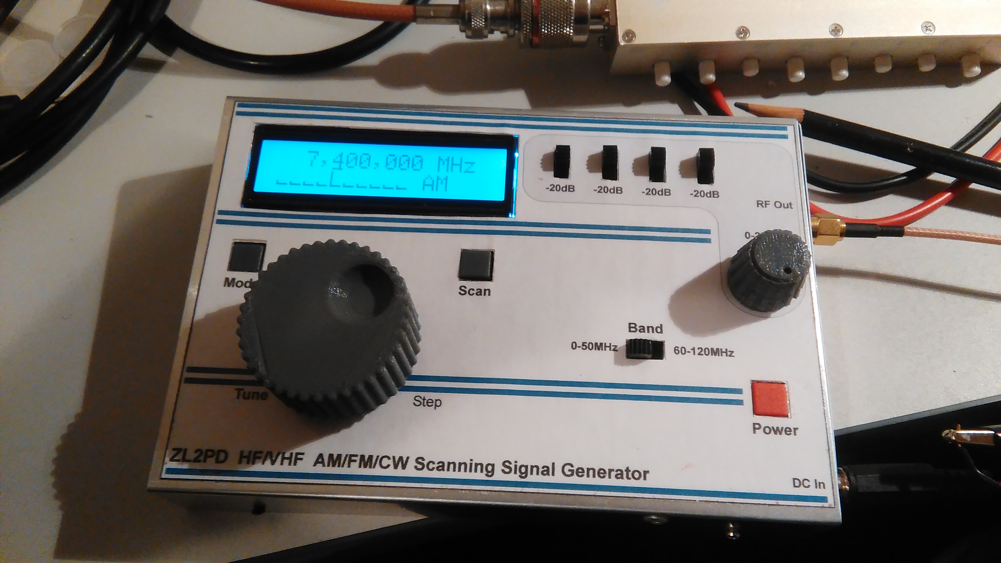
Figure 1 : The signal generator alive and operating on my workshop bench
During the development process, I built five prototypes, the last two being identical to the version described in the magazine. Of these, the final prototype featured some minor improvements in the PCB layout and shielding. It also allowed for some additional detailed testing.
Based on all of the builds, I can confidently predict that it should cost less than $US50 to build. Many of my parts came from the usual Chinese providers. Those buying components and materials from local retailers may spend up to twice this sum.
All of the details are available in the two magazines and on the Silicon Chip website. The design was originally published in the June 2019 issue of Silicon Chip, and a year later in the UK's Practical Electronics magazine. The first described the circuit and many of the features, and showed results of measurements made on the prototype using a spectrum analyser. The July 2019 issue described the construction of the signal generator.
Features and Specifications
The
specifications are summarised here:| Item | Specification | Comments |
| Coverage | 100kHz-50MHz, 70MHz-120MHz | Usable up to 150MHz |
| Tuning Steps | 10Hz to 1MHz in decade increments | User-selected |
| Accuracy & stability | Within 150Hz at 30MHz (typical), 0-40°C, 0-80% humidity | Can be enhanced with software calibration |
| Output level | -93dBm to +7dBm (approximate) | 50 ohm termination |
| Attenuation steps | 0-80dB in 20dB steps + 0-20dB (variable) | |
| Output socket | SMA | |
| Spurious & harmonics | Typically better than -30dBc | Within specified coverage frequency range |
| AM | 30% modulation @ 1kHz | |
| FM | NB (12.5kHz spacing), 1.75kHz deviation @ 1kHz (60%) | |
| WB (25kHz spacing), 3kHz deviation @ 1kHz (60%) | ||
| BC (12.5kHz spacing), 50kHz deviation @ 1kHz (60%) | Suitable for standard broadcast FM receivers | |
| Scanning | Programmable start and stop frequencies | 1kHz resolution |
| 10, 20, 50, 100, 200 or 500 steps/sweep | Auto step size calculation | |
| Display | 16x2 alphanumeric LCD | |
| Power control | Soft on/off switch | |
| Controls | Two knobs and eight switches | |
| Power supply | 9-12VDC at 250mA | |
| Dimensions | 160 x 110 x 25 mm (excluding knobs) 160 x 110 x 45 mm (including knobs) | |
| Weight | About 250g |
Questions and Correspondence
All
of the details are available from the Silicon Chip or Practical Electronics magazines and their
website. Please direct any questions you may have about the design
through Silicon Chip and they will be answered as promptly as possible.
I do have a 'day job', and the great staff over at Silicon Chip have a
magazine to run, so please be patient.Problems and Solutions (Added: February 2020)
Following the original publication in Silicon Chip, there were two problems experienced by some builders:- The signal generator would not always turn off, and
- Some builders experienced very erratic rotary encoder response
The power to the signal generator is turned on and off via a momentary pushbutton. Here is the section of the circuit which carries out this function with the ORIGINAL component values published in SilChip shown. (PE in June 2020 showed the CORRECT/UPDATED values)

When the pushbutton is pressed to turn the power off, Q5's base voltage should discharge into the 1uF capacitor via the 1k series resistor (R34 on my circuit above). With larger capacitors on the switched output voltage rail, Q5's base voltage is held higher via the other 1k resistor (R33) which connects between the switched DC rail, the pushbutton, and the 1k series resistor feeding Q5's base (R34).
The Solution:
Replace R33 (1k) with 10k (R33 being the resistor from the collector of Q4 to the pushbutton). This increases the time available for Q5 to turn off.
If R33 is increased to a much higher value than 10k, a tempting solution, then another problem occurs - Q5 will not turn on at power-up. Alternately, if R33 is increased just slightly above the suggested 10k value, then the range of DC supply voltages that the Q4/Q5 will reliably switch into reactive loads reduces.
2. Rotary Encoder Issue
Some builders found that the tuning control was erratic and unresponsive. Despite extensive tests with a wide variety of encoders available to me, the problem could not be identified. Fortunately, one reader was kind enough to send his signal generator board to me for testing and analysis. Almost immediately, the actual cause of the problem was identified.
Types of Rotary Encoders
There are two main types of rotary encoders; position and incremental. The former, relatively common in industry but relatively rare in hobbyist applications, use Grey Code or a similar scheme to output a precise linear or angular position.
The other type of rotary encoder, almost universal in the hobbyist world, is the incremental encoder type. They produce a pair of phase quadrature output signals (i.e. the outputs are 90o phase shifted from each other), as shown below.
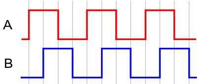
A B
0 0
1 0
1 1
0 1
0 0
1 0
1 1
0 1
If the control is turned in the other direction, counterclockwise, then the waveform changes so that now, the blue output leads the red output.
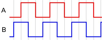
A B
0 0
0 1
1 1
1 0
0 0
0 1
1 1
1 0
This change of logic states e.g. (0,0) to (0,1) or (0,1) to (1,1) etc, can be detected in software, and can be used to determine the direction of rotation and the number of turns..
Depending on the way a rotary encoder is made, it may or may not have ‘clicks’ or 'detents'. These are locations where the rotary encoder will naturally halt as it is turned. Low cost encoders typically have 12 to 24 such clicks per turn. For example, your PC mouse wheel usually has one of these encoders, as do many volume controls on consumer radios. Conversely, high quality relatively expensive encoders usually have no ‘clicks’. Examples of these include the main tuning control on a ham radio transceiver.
It turns out that there are two types of incremental rotary encoders. The first, and in the past arguably the most common, results in the encoder resting in one of the four possible quadrature output states shown in the tables above. I call this the 'level' type of incremental rotary encoder. An example of its two outputs taken from the vendor's datasheet for one of these encoders is shown below. the dotted lines mark the 'detent' locations. You can clearly see (I hope) that the encoder will stop on a specific logic level matching those in the tables above.
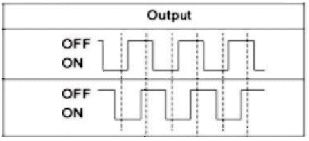
However, there is another type of encoder, seemingly almost universal in current consumer products. It produces a short pair of quadrature ‘pulses’ as the control is rotated, but rests (at the ‘click’ point or 'detent') in an open-circuit state.I call these the 'pulse' type incremental rotary encoder. An example from a datasheet for one of those encoders is shown below:

The vast majority of low cost encoders supplied from China appear to fall into this latter category. This is the type of encoder used on all of the signal generator prototypes and on all of the designs described on my website, as far as I can tell.
There are several interesting features of these latter 'pulse' encoders. First, as noted, the encoder will always rest open circuit. Secondly, the pulse timing can vary considerably. The diagram shows the clockwise rotation with a 'sort-of-but-not-exactly' quadrature-ish relationship between the two waveforms. The pulse timing shows significant differences if you look closely. Interestingly, however, these encoders are surprisingly easy to handle in software.
.
As far as I can tell, component suppliers may offer either type, and they don't necessarily know, or can tell, which is being supplied. Equally importantly, they look identical, and may have exactly the same external markings, despite the fact they operate in very (very!) different ways.
Encoder Solution:
With the fundamental encoder problems accurately identified, the solution was relatively simple. In addition to the clock initialization change, a new encoder detection interrupt routine was provided to Silicon Chip (and Popular Electronics) for builders to download to account for the two different types of incremental rotary encoders.
Depending on the encoder type, an additional 100k resistor may need to be fitted under the PCB, from pin 28 of the processor to ground, to tell the software which encoder type is being used. Omitting this resistor tells the processor that the 'level' type encoder is in use. Fitting it tells the processor it is using the 'pulse' encoder. The presence or absence of this resistor does not affect the normal function of the pin which is also used to control the AD9850 module.
Final Comments
I
hope you get as much pleasure from building and using this signal
generator as I continue to do. I use it regularly on my test bench for
a wide variety of tests and measurements. Resolving the two problems that affected some builders took longer than I would have liked - work and travel getting in the way - but getting them resolved has been very satisfying.
Downloads:
Please refer to the Silicon Chip magazine website at www.siliconchip.com.au or the Practical Electronics website at www.epemag.comWant to go back to the main page? Click here to return directly.