
Menu:
Version:
Sept 16, 2015:
Revised: v1.1
Build a Compact Digital OBD-II Speedometer Gauge
What
happens when sunshine on your dashboard stops you from seeing how
fast you're going? I came up with a cheap solution to this deadly
serious problem on my
Mitsubishi Pajero. This design can also form the basis of
all sorts of
other OBD-II based gauges
for your car.
Introduction
I reckon Mitsubishi might just be trying to kill me.OK, sure, that’s something of an exaggeration. But, after driving my new Mitsubishi Pajero for a few days, I was rapidly coming to that conclusion. Mitsubishi seemed to have made a car that could, just maybe, get me very quickly killed around here.
A little background. I work in Saudi Arabia, and when it comes to driving, Saudi Arabia is a world leader. It’s probably one of the most dangerous countries in the world to drive a car. On average, 24 people die every day on the roads here. Some think this count to be understated. I've been told that if a traffic accident-related death occurs in the ambulance or after the injured party has reached hospital, that death not included in these numbers. If that’s true, then the actual number of deaths from driving might be as high as 30 per day, or perhaps even more.
But let’s assume those official figures are correct. By the way, that number is up from 17 deaths per day about five years ago. Clearly, then, the efforts to improve road safety in Saudi Arabia, such as new red light and speed detection cameras, are having an effect. Maybe not in quite the direction that might be assumed.
But just how bad is it really? Table 1 suggests driving in Saudi Arabia may be up to fifteen times more deadly than my home country, and perhaps over twenty times more lethal than the UK. Yikes!

Note: Saudi Arabia statistics are based on 2015 local press reports while the
other statistics shown are from those national authorities, typically for 2012
other statistics shown are from those national authorities, typically for 2012
Table 1 :Selected International Road Death Statistics
But what’s all this got to do with my 2015 Mitsubishi Pajero? Well, just before summer (2015), I needed to buy a new car. After a lengthy search, I decided to purchase the Pajero. It looked fine in the showroom. (It’s pretty much impossible to arrange to test-drive new cars in Saudi Arabia, in case you’re wondering, no rentals were available for me to road test, and my mates drive other brands)
Once I got it out on the road, I quickly discovered that it was impossible to read the speedometer while driving almost anytime during the day. Everything else was just fine, thanks. Just that speedo. Turns out, other Pajero owners complain about this too, judging from various web forums.
Unlike most countries where this problem might just be a bit of a nuisance, this can present a deadly risk in Saudi Arabia. Dangerous driving is commonplace here as you might have guesed from those statistics. Basic road rules seem to be largely ignored. The result is driving mayhem, with speeding and unpredictable driving a constant risk. Hardly a day goes by on my regular commute to my office when I do not see at least one significant accident. (140kph on a suburban street? Exiting a motorway using the ON-ramp? Driving on the wrong side of the road? Road bullying at 120kph on busy multi-lane highways? Unannounced turns across multi-lane intersections? Driving through red lights in rush hour during the day? Yes, all regular events here)
And then we have the speed cameras, introduced to address some of these problems. Some camera locations are well known, such as at major city intersections where driving through red lights is otherwise routine. Other speed cameras, however, are randomly moved from place to place along busy highways, and sometimes partially hidden. Many of these are placed periodically at known danger spots.
As cars approach a known fixed camera site, they all obediently slow down. However, with the randomly placed cameras, brakes often get applied late and hard. Cars following too closely, another common practice, abruptly and unexpectedly swerve to avoid the braking vehicles. The results can be quite chaotic. Multiple car pileups are common, frequently close to these speed cameras.
In general, then, it’s vitally important to keep a close eye on your speedometer. The problem I found was that the Mitsubishi’s instrument cluster design makes that practically impossible during the day. The instrument cluster uses black plastic pointers topped with a thin red line set against a greyish background with shadowed pale grey numerals. Mitsubishi’s designers then placed these gauges down the bottom of a pipe-like cylinder. The result in daylight is a shambles. That instrument panel becomes difficult to read, even with the panel backlights turned on. When wearing sunglasses, essential for driving here most of the year round, those instruments become utterly impossible to see.
If a driver is struggling to read the speedo, perhaps looking for a longer than desirable time to check their speed, or trying to keep a close eye on the car’s speed while approaching a speed camera, trying to avoid the erratic drivers around them, you can begin to see my problem. In my opinion, Mitsubishi delivered a gilt-edged invitation to an accident, or worse, with this instrument cluster design.
I had to sort this problem out, and quickly.
Possible Solutions
One
option for me was to buy one of the many “head’s-up display” (HUD)
speedometers advertised on well-known websites. These display speed and
other vehicle parameters by reflecting the light from a bright LED or
LCD digital display onto a special semi-transparent film placed on the
inside of the vehicle’s windscreen. Reviews are mixed, some noting
blurred displays, and others noting the display is often washed out by
bright sunlight. A further common complaint is the slow update rate –
About once per second, too slow for my application. And they are not
particularly cheap. Another option was to mount a small cellular phone on the dashboard to show the required information. This could be connected with some form of interface to determine my car's speed. However, I was not able to find a phone small enough to fit neatly on the dashboard nor software that could display just one or two parameters clearly.
One design I came across during my search of a solution used a low cost GPS receiver module, a small processor, and a display to report vehicle speed. Again, the relatively slow once-per-second update rate and the need to display speed accurately in tunnels, under bridges and in long underpasses, places where GPS satellites cannot be seen by the GPS receiver, ruled it out for me. Speed cameras are located in such spots in Saudi Arabia, or worse, just on the bright sunlit exit of a dark tunnel. (Amazing to see how far up the tunnel wall a large 4WD crashing at 100+kph can climb before gravity takes over...)
So, after a fairly comprehensive search, I decided to design and build this simple low-cost design. It uses a compact high contrast OLED LCD, a small microcontroller, and a widely available OBD-II interface. A purpose-designed 3D-printed enclosure I made for the display completes the package. Its small size and ultra-thin form-factor allows it to be placed almost anywhere around the dashboard to suit the driver.
The OBD-II Interface
All
vehicles built since about 2008 are required to be fitted with an
OBD-II interface. “OBD” stands for “On-Board Diagnostics”. The OBD-II
system follows a set of industry standards, including the connector and
its location, close to the driver. It uses a high speed two-wire bus
which connects a variety of subsystems. Communications across this bus
typically run at 500kbps although bus speeds may range from 125kbps to
900kbps. This OBD-II bus can therefore be used to access a wide
variety of vehicle information including vehicle speed, engine rpm, oil
temperature, and a variety of other details.Low cost OBD-II interfaces are available from the usual Chinese sources. These allow users to obtain information from the OBD-II system via USB and Bluetooth. One of these, an ELM327 compatible OBD-II to USB interface, was purchased for this project. it cost me about $US5. Simple serial data commands can be used with this interface to interrogate the car’s ODB-II systems, typically at 9600bps or 38,400 bps, although serial speeds up to 115,000 bps are also possible.


Figure 1 : Typical OBD-II modules – USB (left) and Bluetooth (right)
Either of these OBD-II modules can be plugged into the car’s OBD-II system. The OBD-II connector is usually located under the dashboard, near the driver. Depending on the type of OBD-II module purchased, it then connects either via a USB cable or Bluetooth (or occasionally WiFi) to a laptop, tablet or mobile phone, as appropriate.
In my case, I decided to use the USB cable version. I removed the USB cable, and mounted an additional microcontroller into the module. A short cable was added to connect the new microcontroller to a tiny LCD mounted on the instrument cluster. Then I wrote some software to make it all work.
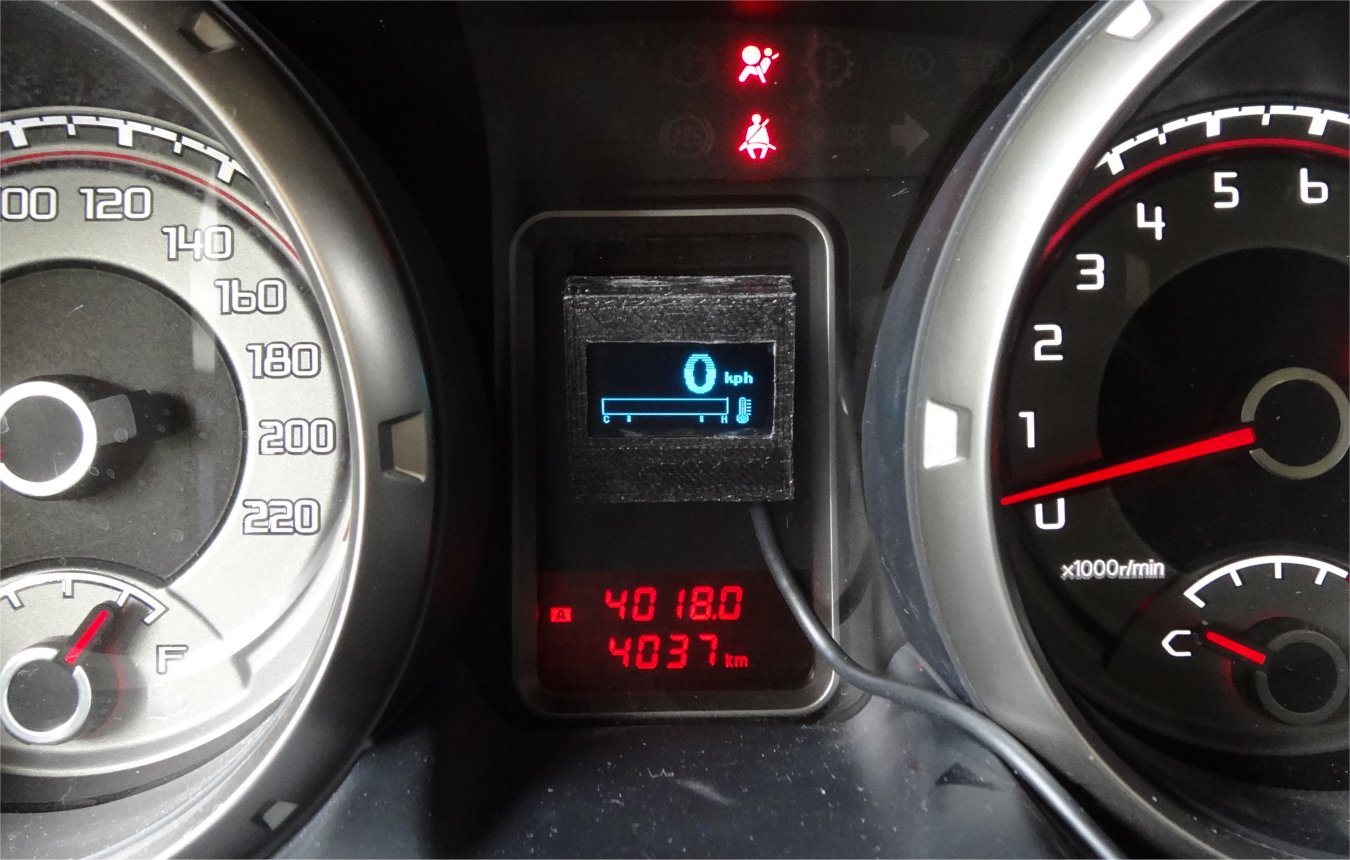
You can see the display operating in the photo at the top of the page. This bright LCD display shows the required information immediately in front of the driver (me!). While it’s a small LCD, the contrast on these OLED graphics LCDs is simply superb. It readily permits the required information to be seen at a glance, or from the corner of my eye, without effort.
The interface with the OBD-II module is handled by an Atmel ATtiny85 8-pin microcontroller. This is fitted inside the original OBD-II module. Its compact 8-pin package, along with the slim LCD and the compact 3D printed purpose-designed 3D-printed display enclosure, makes for a safe, cheap and easily readable dash-mounted accessory. The unwanted USB cable from the ODB-II module was discarded.
Inside the ODB-II Interface Hardware
Almost
all OBD-II ELM327 USB interface contains three chips; A chip to handle
the hardware level interface to the vehicle’s CAN bus, the ELM327
microcontroller and a USB interface chip. Functionally, it boils down
to this:
Figure 2 : Block diagram of ELM327 USB module BEFORE modification
This ELM327 module is modified slightly in my design to allow the ELM microcontroller’s serial lines to be connected to the new ATtiny85 instead of to the serial/USB chip. That chip is typically a Chinese-made PL2303 or CH340. After the modification, this USB chip is no longer used.

Figure 3 : Block diagram of ELM327 USB module AFTER modification
There are several similar designs described on the web. However, these all assume the ELM327 USB interface contains a standard ELM327 processor. This is very rarely the case now, most having been replaced by low cost Chinese clones. Several of those other designs I came across also made a similar modification to the serial I/O lines on the processor, but they also added a further change to force the ELM processor to slow its serial comms down to 9600bps. Here's the problem: That’s does not appear to be possible with the latest clone processors. With their different pinout, as far as I could determine, it did not appear possible to make the same change to reduce the serial I/O speed. So, my design rose to the challenge of using the very much faster standard 38,400bps serial speed.
All of the graphics information for the OLED LCD must be sent to it by the ATtiny85. Unlike low cost 2 line x 16 character alphanumeric LCDs, the OLED LCD contains no character or graphics lookup tables. However, it can take some time to send all of the required data to the display over its I2C bus. To speed up the process, the ATtiny85's internal clock operates at 16MHz, and LCD data is only sent to the areas of the display which require a change. This ensures a swift flicker-free display.
The 128 x 64 pixel OLED display can support a wide range of display graphics. I designed the large speed digits using a 40 x 32 pixel per digit format for high readability. The associated “kph” or “mph” units, selected using an on-board jumper, are displayed within a similar pixel space, but using a slightly smaller font size. The speed digits are updated around ten times per second to ensure the best possible response time.
The remaining 128 x 24 pixel space is used for a bar-graph display. This is used to show a slowly changing parameter. I chose to show the engine coolant (i.e. oil) temperature. A small “thermometer” icon completes this section of the display. Because oil temperature changes gradually, the bar-graph is updated about once every 30 seconds.
This bar-graph also features an expanded temperature display format. Temperatures are compressed slightly at the hot and cold ends of the bar-graph to provide more detail over the "normal" temperature range of interest. That means the driver will be able to react more quickly to significant changes in oil temperature.
The OBD-II system allows oil temperature to be reported over a range from -40C to +215C. Mitsubishi’s manuals indicate that the ‘normal’ range for the engine oil temperature is around 70C to 90C. That normal range is centred within an expanded 60C - 120C range across about 50% of the bar graph. (The upper numeric values shown in Figure 4 are not shown on the OLED, only the lower C, H and normal boundary markers)

Figure 4 : Oil temperature bar graph scale
Schematic and Circuit Description
The schematic shows the circuit details for the ELM327 interface modification. It's a very low compoment count modification.
Figure 5 : Schematic details for ELM327 display modification
Power for the ATtiny85 is obtained by tapping onto the onboard 5V regulator inside the ODB-II USB interface. It has a more than adequate margin to cope with the very modest additional current requirements of the ATtiny85 and the OLED LCD. Protection against potential voltage spikes on the incoming 12V OBD-II supply, particularly when starting the vehicle, is already fitted in the OBD-II interface. This also protects the ATtiny85 and the LCD from possible damage during vehicle starting.
The ELM327 processor’s RxD and TxD lines connect directly to the ATtiny85 microcontroller after the modification. Commands are send via this serial interface to the ELM327 chip by the ATtiny85 to request speed and other information. The response from the ELM327 chip returns from its serial output. The data is then checked and processed by the ATtiny85 and sent to the LCD for display. The OLED LCD uses a standard I2C two-wire interface comprised of a serial data (SDA) and a serial clock (SCL) line.
A small jumper is available on one ATtiny85 pin (Pin 6) to determine if the speed is displayed in metric (kph) or legacy (mph) units. Leaving this link open places the speedometer in the metric (kph) mode.
One problem remains unsolved. Power to the OBD-II interface and add-on electronics must be manually turned on and off. The OBD-II connector does not contain any wiring to indicate when the ignition switch is on. The battery supply is wired directly to the OBD-II socket and is always on. If the OBD-II interface is left powered up at all times, the car’s battery will eventually run flat. For simplicity, a simple miniature toggle switch turns power on and off to the OBD-II hardware.
There is a spare pin remaining on the ATtiny85 which is reserved for a possible future update to this arrangement.
Parts List
These are the parts you’ll require:
Table 2 : Parts list for the speedometer
All the parts required should come to less than $20 if purchased new. In my case, only the ELM327 USB module and OLED LCD had to be purchased. The remaining parts came from my parts bin.
Disclosure Statement: I get no commission, free stuff, or any preferential treatment from any of the companies mentioned here. There are other suppliers who are probably equally suitable. This table is simply a useful way to show examples of the parts used.
Construction
The
prototype was assembled onto a 12 x 10mm scrap of prototyping board.
The ATtiny85, bypass capacitor and the LCD connector are all fitted on
this board. I used a socket for the processor. A four-way pin connector
is then fitted to the board for connection to the display. I cut down a
4-pin header from a longer 20-way strip, and cut down a matching 4-way
connector for the cable-side from its matching 20-way socket. Other
options exist, including simply soldering the cable directly to the
board.I didn’t design a PCB for this project – It was so simple, it just wasn’t worth it for a one-off project like this. In any case, it's nearly impossible to make a PCB here. Of course, if I was making 100 of these, I certainly would whip up a PCB, and I’d probably use SMD parts to make it even near-microscopic in size.Anyway, back to my story...
The ELM327 OBD-II USB interface is then opened and modified. The front panel artwork is peeled off to reveal the four screws that hold the assembly together. The OBD-II connector and USB cable each plug into the PCB. Take a careful note of which way around the OBD-II connector goes, and then remove both it and the USB cable from the PCB. The PCB can then be removed from the enclosure.
The next step is to disconnect the USB chip’s TxD pin from the circuit. If you have a module fitted with a PL2303, then carefully heat pin 1 of the PL2303 chip with a soldering iron fitted with a fine tip, and then very gently lift the pin up off the PCB track. (If you have the CH340G USB chip, lift pin 2 off its PCB pad instead)

Figure 6 : Modification to pin 1 of the PL2303 USB chip in the ELM327 USB module
This modification ensures there is no contention between the TxD output of the now-unused USB chip and the added TxD output coming from the ATtiny85.
Now, drill a small hole in the enclosure cover for the small toggle switch. I used the smallest switch I could find, and it easily fitted into the box. Then modify the +12V supply wiring as shown in Figure 7.

Figure 7 : Modification to switch the +12V supply in the ELM327 USB module
I found it easiest to begin by removing the white wire from pin 16 of the OBD-II connector. This wire normally connects directly to the 8-way connector which plugs into the ELM327 board (I removed it from its box during this step) I then soldered the wire to the switch. I then added a short piece of stranded yellow hookup wire between the other side of the switch and pin 16 of the ODB-II connector.
Solder four short wires to the ELM327 PCB for the ATtiny85’s +5V, ground, RxD and TxD connections, and connect these to the ATtiny85 board. This wiring is shown in Figure 8 and Figure 9.

Figure 8 : Adding RxD (Green), TxD (White) and Ground (Brown) wires to the ELM327 PCB
That green wire (RxD) is soldered on to the SMD part as shown, and then goes to pin 2 on the ATtiny85. The white wire (TxD) is soldered onto the adjacent part, and then goes to pin 3 on the ATtiny85. The brown wire is soldered into the centre hole on the left hand edge of the ELM board above, and it then goes to pin 4 (ground) on the ATtiny85.

Figure 9 : Adding the 5V wire (Red) to the underside of the ELM327 PCB
Pause if necessary now to program the ATtiny85 and to make the 3D printed enclosure for the display.
Programming the ATtiny85
There are (at least) two ways to do this. The first option I’ve used is to build and use the Ponyprog
programmer. However, this requires your computer to have an RS-232
interface. Those are exceedingly rare these days, although I have made
the programmer work using a USB-RS232 interface cable. I strongly recommend you use the second method, using a USBasp programmer.
Ready-to-use USBasp programmers can be purchased from any number of Chinese suppliers over the web, usually for less than $US3 delivered. Examples include Banggood (SKU064451 or SKU131560, for example) and Hobbyking (e.g. Part 381000147). Note: These part numbers vary periodically.
GUI software to drive the programmer is available (free) from various websites. I have used Khazama extensively, but more recently, I’ve also found Extreme easy to use with this USBasp programmer.
Unfortunately, these websites seem to provide very limited support for anything more than a limited range of basic AVR processors. For that reason, I’ve either had to locate or, in many cases, had to develop several updated files for these software packages to add a number of the more commonly used processors. To help others in the same situation, I’ve included the updated files below in the Download section for the Extreme software. Once the original Extreme software has been downloaded and installed on your computer, just unzip the ExtremeFiles.zip file I’ve included below, and copy the two unzipped files (chips.xml and fuselayout.xml) into your <Program Files/eXtreme Burner – AVR/Data> folder (That’s the location of these two files on my Windows 7 computers anyway. Other installations may vary this) to replace the original files of the same name found in that directory.
Note: Computers vary, and nothing is guaranteed for you and your computer. Take care to backup your existing files before adding any new software like this to your computer. I make no warrantees or guarantees for any of this stuff. It’s all at your own risk. It worked for me, and it should work for you. Not all software I try works, and the same thing will certainly be the case for you.
Two steps are then required to program the ATtiny85 with the USBasp programmer – The flash memory must be programmed with the program software, and the processor’s fuses must also be correctly programmed. Details of the fuse settings are found at the start of the source code file.
I programmed the ATtiny85 using a secondary board which has a socket for the chip and the 6-pin programming header. There was no room for the programming header on the little board I added to the ELM327 module but you are free to add the programming socket to your version if you wish. The circuit diagram for my adapter is shown in Figure 10 just in case you need to duplicate it. The resistor and LED are optional. They were added to show me when power has been applied to the programming adapter.

Figure 10 : Optional ATtiny85 programming adapter
(Note: The
ATtiny85 to be programmed goes into socket SKT1. The USBasp programmer
is plugged into the 6 pin plug J2. 5V power comes from the programmer
via J2 so J1 is normally unused)If all of this remains a mystery for you, there are some helpful tutorials on this topic that can be found on the Adafruit and Instructables websites.
Making the 3D Printed Enclosure
In
order to retain the advantages of the compact OLED LCD, I also designed and made
a simple plastic enclosure to hold the display. When it clips shut, it
also clamps onto the connecting cable. I printed it using standard
black PLA plastic. The chosen colour (black) as well as the overall compact
size of the enclosure allows the display to be placed almost anywhere
around the instrument cluster.
Figure 11 : 3D printed display enclosure – Design
The front and back sections comprising the display enclosure were printed on a low cost Printrbot Simple Metal 3D printer using PLA fibre (No heated platform). It took less than 20 minutes to produce the required parts. The required STL-format files are available for download below.

Figure 12 : 3D printed display enclosure – OLED LCD in place with soldered cable
The cable running to the ATtiny85 board in the modified OBD-II module is first soldered to the OLED display. The OLED display then drops directly into the front half of the display enclosure. There is no need for any additional hardware. The back panel then just clips into place and holds the assembly together. It simultaneously clamps the 1.2m long connecting cable. (The cable cutout/slot in the case goes to the bottom-right corner when viewed from the front)
I used standard 4-conductor telephone cable initially because it was to hand. I later swapped it for a less-visually intrusive small black cable. As noted earlier, the other end of the cable should be soldered to a 4-way socket to plug into the ATtiny85 board.
You may need to make your cable slightly longer or shorter depending on where you decide to place the display. Measure first (I used a piece of string to work out the cable route and length), then cut your cable to the right length allowing a little extra for the connector and board connections.
Completing the Construction
Carefully
plug the display cable into the ATtiny85 board. Check it’s the right
way around! Then replace the OBD-II PCB and ATtiny85 board into
place and close up the OBD-II enclosure. If necessary, use a drop
or two of hot glue to hold everything. I didn’t require it in my
version, but you might find it useful. Finish up by mounted the display in place on the dashboard with a scrap of double-sided sticky foam.
Operation
Make
sure the power switch is off on the OBD-II module before plugging it
in.
Turn the power on and confirm the power-on “splash” screen is shown on
the LCD. It briefly shows a suitable logo and label. The display then
reverts to the speed and bar-graph display. Start your car and do a
careful test drive. (Do I need to add a warning about testing this in
an area without other drivers, small children and large camels?) The
module will now report your
speed and oil temperature.The oil temperature bar graph display is initially blank since no data is reported by the OBD-II system. After about 30 seconds, the bar graph is updated to show the initially ‘cool’ engine oil temperature. The temperature rises steadily into the ‘normal’ area of the graph within a minute or two, at least for my car.
When I arrive at my destination and turn the ignition switch off, I then turn off the toggle switch to turn off the speedo.
Here’s a picture of it all running during my first tests with a temporary ugly white cable.

Figure 13 : The display with a temporary white cable used for testing
The engine is running, the instrument cluster backlights are on (Yes, you CAN see the instruments clearly here, but it was about 5pm, close to dusk, and almost no sunlight was falling onto the dashboard). The speedo is reporting 0 kph (I was stationary while taking the photo!) and the oil temperature is nearly centred in the ‘normal’ range.
I later tested it against my GPS-derived speed at a range of speeds (with a helpful assistant) and found it to be within 1kph across the range. Adequate for my purposes.
Changes and Modifications
Yes, it’s possible to change the
software to display all sorts of other OBD-II parameters. However, the car’s OBD-II system must support the
specific parameters you wish to display. VERY IMPORTANT: |
| OBD-II parameter support varies between vehicle manufacturers. While all manufacturers seem to support the basic set (i.e. speed, rpm, oil temperature, and so forth), other OBD-II parameters may not be supported. |
One example is the OBD-II parameter which reports the fuel tank level. You might think this would be widely supported. Not so. While Mitsubishi measures the fuel level using its on-board computer, and then displays the fuel level on the (impossible to see!!) instrument cluster, the fuel tank level is NOT available via Mitsubishi’s ODB-II interface. Why? Who knows! Other vehicle manufacturers, however, do provide access to this parameter, but they then omit others.
Prior to starting out on the software for this project, I began by testing the OBD-II USB interface I purchased, using my laptop and some free ODB-II monitoring software I downloaded from the internet. This allowed me to quickly confirm which parameters were available, and the approximate range of values typically reported by the vehicle through the interface. That’s when I discovered the fuel tank level was not available on the Mitsubishi Pajero’s OBD-II system.
It is possible to determine the fuel level by using other available Mitsubishi OBD-II parameters by making a few additional calculations. However, that approach would also have required me to add another user pushbutton to this design, to tell the ATtiny85 when I had just filled the tank. There's no way to detect that remotely. I’d also have had to add some extra software to save the current tank level to non-volatile EEPROM in the ATtiny85 whenever the power was turned off. Adding the fuel tank level meter to the design very quickly started to spiral out of control, even for me, so I dropped that idea, and opted for reporting oil temperature instead.
Assuming the parameter you want is available via the OBD-II interface, and you want, say, to display your engine’s coolant temperature as well as speed, that’s perfectly possible with this design. In fact, that’s obviously just what I did, adding oil temperature as a moving bar graph to the lower third of the OLED display.
The source code is available below for those wanting to make changes to this design, and the comments in the source code should make implementing these reasonably easy. I wrote all of the software using Bascom, a Basic-like language for the AVR family of processors. For me, it’s a much faster method than using assembly code (or C for that matter) and far easier to figure out and modify later when I revisit some software.
So, changes are readily possible. For example, it’s also possible to replace the bar graph with a couple of other, smaller, numeric displays. You could add a numeric display for RPM, say, and the time to reach 100 kph, for example, instead of the speed and oil temperature I used here. All of the code blocks exist in the source code, and they can be reworked to show that detail, if required.
It’s also quite easy to add logging functions to display selected information on a graph on the display. Finally, there is also a spare pin (pin 1) available on the ATtiny85, and free code space, to add more features. Examples include adding a flashing LED to indicate when your speed is above some set value, or a pushbutton to select one of several display screens or display formats. The current code fills about 75% of the available 8k flash memory.
I have thought about adding an automatic power turn-on/off function which, in hindsight, looks pretty simple to add. But that mean I'll have to dive back into the finished module. Again. And I need it every day. Hmmm....
Incidentally, I also purchased a cheap Bluetooth version of the OBD-II module at the same time for another $US5. At the utset, I wasn’t sure whether I’d use the USB or Bluetooth ODB-II module for this design. In the end, I designed and built the USB module version first, which I’ve documented here. However, in the process, I also managed to design a significant proportion of a similar, even more compact, version based on the Bluetooth OBD-II module, complete with auto power-on/off. If I get some time, and if there’s any interest, I might finish it and document it here too.
No, I’m sorry, I am not able to make special one-off software changes for you. I have a regular job and I prefer to use my spare time to develop new stuff. The software for this design is thoroughly commented to allow you (or an experienced programmer friend) to make most changes you might want, quickly and easily.
Conclusions
This
low cost compact OLED-based OBD-II display has solved my problem completely.
Driving may still be incredibly dangerous in this country, but at least
trying to read the Mitsubishi speedo will no longer add to that risk for me. I’ve
found that I can easily read this display in all light conditions,
including full direct summer sunlight, and through my sunglasses.
Success.All of which makes me wonder how the Pajero’s instrument panel ever got designed and built like this in the first place. Unless Mitsubishi's designers have never seen the sun. Yep, that might explain it.
Downloads
 Software (HEX file for those just wanting to program their ATtiny85 and the Bascom source code for those wanting to modify the code) (Fuse details are documented near the top of the source code) 3D printer file for the dash-mounted display enclosure (STL-format) Extreme USBasp files (ExtremeFiles.zip)
Want to go back to the main page? Click here to return directly.