
Menu:
Version:
Feb 17, 2016:
Revised: v1.0
Single Cell Li-Ion Battery Monitor
 This
module monitors the cell voltage on a Li-Ion cell to allow reporting of
cell capacity and cell voltage in addition to a flashing recharge
alert.
This
module monitors the cell voltage on a Li-Ion cell to allow reporting of
cell capacity and cell voltage in addition to a flashing recharge
alert.
Introduction
Li-Ion cells with a variety of capacities are available for low prices from many sources . They are also turning up in a variety of recycled products around here.I decided to use one of these to power a GPS frequency reference recently. it's usually powered from a DC power supply, but it's useful to have a battery backup supply for it in case the power fails. Also, the battery allows me to use it in different places without having to worry about carrying the power supply along with it. The internal Li-Ion battery can run my GPS frequency reference for up to four days between recharging cycles so it doesn’t need to tie up an AC wall socket permanently.
I use a recycled 5V USB mobile phone charger to supply the reference and to recharge the battery. It only takes a couple of hours to recharge the battery. I added one of the widely available TP4056-based Li-Ion charger modules into the GPS reference to manage the battery recharging process. This charging module, shown below, has two LEDs to indicate progress. A red LED shows when it is charging while a blue LED indicates when charging is complete. Cheap, simple and effective.
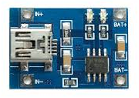
Figure 1: Typical TP4056 Li-Ion charger module
Unfortunately, these modules don’t indicate when it is time to recharge the battery. Other versions of these modules include a low battery disconnect feature, but even those boards do not have a “low battery” LED. I can easily forget to plug in a charger at the right time so I needed some way to monitor the Li-Ion cell and alert me when to recharge the battery. That's the reason behind the development of this battery monitor.
Li-Ion Battery Voltage Characteristics
The nominal Li-Ion cell voltage is about 3.7 - 4.2V. During recharging and immediately following charge, the cell voltage rises to 4.2V to as high as 4.4V. Once charging stops, this voltage falls as the battery’s energy is used. The following diagram shows the typical cell voltage.
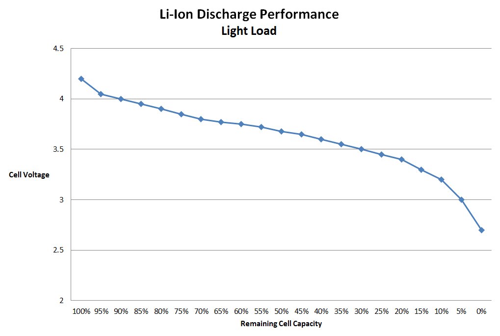
Figure 2 : Typical Li-Ion cell voltage and capacity for low load currents (!!)
It’s very important to ensure that Li-Ion cells do not discharge below about 2.7V to avoid cell damage. In any case, and as the above graph shows, the battery’s capacity is almost completely used up by the time the battery terminal voltage reaches 3V or so. Actually, recharging is probably a good idea once the cell voltage falls below about 3.2V since cell voltage falls rapidly after this point is reached.
But what’s the easiest approach to indicate this to the user?
Method 1 – Use an LED
The first method I tried was to use a red LED and a TL431 reference. The circuit is shown in Figure 3.
Figure 3 : Simple Li-Ion low battery indicator
It’s quite simple in operation. The red LED will come on when the cell voltage is above 2.9V, the voltage I decided was the absolute limit for my GPS reference. Below that voltage, it turns off. This works nicely, drawing 2mA when the battery is around 3V and 6mA when the battery is at or above 3.5V.
However, this ended up being just one more red LED around my increasingly crowded bench. It was also easy to overlook it - I needed to notice that the LED had turned off. I explored some methods to make the LED blink, but the circuit started to get quite complex. Before long, I had a couple of transistors and a few resistors and a capacitor cluttering up the circuit. Hmmm….
Even with a blinking LED to indicate the time to recharge the battery, I discovered that right up until the moment the LED turned on, I had no way to determine the life left in the battery. I needed something a little better.
Method 2 – Use a Microcontroller (of course!)
It’s
cheap and easy to use a small microcontroller to monitor the cell. I
started by trying an 8-pin ATtiny25, connecting up to five LEDs to
display battery voltage in broad steps and blink one (or all of them!)
when it was time to recharge the battery. But that seemed a little
primitive. More LEDs (using charlieplexing) was possible, and I could
even added a small LCD, but that seemed a bit of an overkill for this.
Besides, LCD contrast falls swiftly as supply voltage reduces which
looked problematic too. I settled on using a compact 7-segment LED display which I found in my parts box. It was a low current high efficiency type which would minimize load current. However, that required the use of a larger 14-pin processor, the ATtiny24. The price difference over the ATtiny25 is minimal.
In fact, because the price difference is so small across all of the AVR chips, I just use the largest member of each chip size now – the 8-pin ATtiny85 and the 14-pin ATtiny84, for example. So, that’s why I used an ATtiny84 here. Feel free to use the smaller ATtiny24. It’ll work fine.
Design Description
Here is the schematic of my single cell Li-Ion battery monitor:
Figure 4 : Single cell Li-Ion battery monitor schematic
The voltage of a single cell Li-Ion battery can range from as little as 2.5V (when it is completely and utterly discharged) to as much as 4.4V. That voltage therefore represents the supply voltage for the ATtiny84. It also required the use of the internal 1.1V voltage reference for monitoring the cell voltage. The alternative 2.5V reference will not operate with a supply of the same voltage. The resistor divider (R1/R2 in the circuit above) is used to reduce the cell voltage down to the right range. The chip’s 10-bit analog to digital converter is then used to measure this voltage. Inside the chip, my software converts it to useful numbers including cell capacity and cell terminal voltage.
The 7-segment LED connects to the processor via individual LED segment series resistors. I looked at using PWM to drive the LEDs in the display directly to avoid all of these resistors. While it was possible, in the interest of simplicity, I decided to use them. It simplified the software and reduced the potential radiated electrical noise from the processor. This chip is within a few millimeters of the GPS reference and I wanted to reduce any such possible interference.
A simple momentary push switch is also connected to the processor. This is used to select the 'cell capacity' or 'cell voltage' display modes of the Li-Ion battery monitor.
Operation
At
power-up, the decimal point in the display briefly blinks twice. The
display then remains off to minimize the current load on the battery. Once every minute, the microcontroller measures the cell voltage. If it is below 3.2V, the LED will flash “r” ( for “recharge”) for one second in every ten seconds to indicate it’s time to plug in the battery charger.
At any time, however, the user can press the single pushbutton to obtain more information. A short press of the switch will result in a display of cell capacity. This is a single digit ranging from “F” (for “full” or 100%), “9” for 90%, “8” for 80%, and so forth, until “1” for 10% and “E” for empty or 0%. Capacity below 2.7V is shown as “-“.
Just keep in mind that the ATtiny84 (or tiny44 or tiny 24) is only rated to operate with a supply voltage of 2.7V. However, I found that it worked just fine for me right down to less than 2.3V.
If you press the button for a slightly longer time, the LED display will report the cell terminal voltage. For example, 3.5V is shown as “3.” and then “5”, the latter digit without the decimal point. Voltages above 4.4V are reported as 4.4V and those below 2.7V are reported until the low voltage limit of the processor is reached. At that point, the module will simply stop working. In my case, that was about 2.3V, by which point the LED was starting to become a little hard to read.
Note: I used the “standard” ATtiny84 device rather than the low voltage ATtiny84V chips which will operate all the way down to 1.8V. The standard less-expensive ATtiny84 is satisfatory here because this monitor is for Li-Ion cells which should NEVER be operated at cell voltages below 2.5V.
Since this is a battery-powered device, current consumption is important. In this design, the ATtiny84 uses its internal RC clock which I set to run at 1MHz. This keeps the average current drain between 1 – 2mA depending on cell voltage. The resistor divider used to monitor the battery voltage uses relatively high resistor values to further minimise current consumption. When the LED display is on, current consumption briefly jumps to 40-50mA. However, since the display is only on for a brief period, the average current consumption remains close to 2mA even during the blinking “r” recharge alert period.
It is possible to reduce this further by using a more efficient LED display and higher value resistors (for R3-R10), and by placing the processor to sleep between measurements. This was unnecessary in my case given the average load of the associated GPS frequency reference was about 50mA, and I am using a large 4000mAh Li-Ion single cell battery. The average processor current of 2mA can be largely ignored here.
Software
The software is written in Bascom-AVR, a Basic-like language. At power-up, after the initial LED decimal point blinks to indicate the startup of the software, and unless the battery level is low, the display will remain blank. The processor simply waits for the user to press the pushbutton. Depending on how long the button is held down before it is released, the processor then measures and reports either cell capacity or cell voltage before blanking the display and waiting for the button to be pressed again.
Internally, a background timer interrupts the processor once every 60 seconds. This forces the processor to measure the cell voltage once every minute and check it against the low voltage limit. If the battery voltage is low, the display reports the problem (displaying “r” for recharge) for one second, and then going back to sleep and blanking out the display again. However, once this low voltage state is detected, the background timer is reset for a 10 second wakeup call. That means the “r” display repeats every 10 seconds until the battery voltage is recharged above the low voltage limit. At that point, the timer is reset back to the normal 60 second cycle time.
Since every LED segment is directly connected to a processor pin, no display multiplexing is required. That also considerably simplified the software.
This minimal software all fits well within the capacity of the ATtiny24 so it can be used, if necessary rather than the larger compatible ATtiny44 or ATtiny84 devices. The software, as usual, is available for download from the Download section at the end of this page. The zip file available below includes both the HEX file (for direct programming the chip) as well as the Bascom source code for those wanting to modify the code for their own use.
Details of the fuse settings are given in the software source code. These match the default settings programmed in by Atmel at chip manufacture. That means you don’t have to program the fuses in a new chip. Just write the HEX file to the chip’s flash memory.
Construction
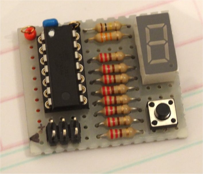
As
you can see from the picture at the top of this page, and in the photo
below, I built my version on a small piece of prototyping board. I used
a 14-pin IC socket for the processor. I also added the standard 6-pin
header to make programming easier for me during software development
(All two hours of it!) Bascom-AVR makes it easy to write simple
software like this quickly. The 7-segment LED and other components were
wired directly into circuit.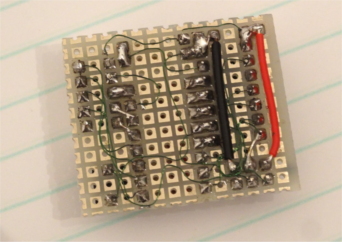 A
pair of “test pins" (That was the description of these pins on the
Chinese website where I purchased them for fractions of a cent
each), each comprising a stiff wire loop passing through either a red
or black plastic ring, are used to connect the module to the battery.
A
pair of “test pins" (That was the description of these pins on the
Chinese website where I purchased them for fractions of a cent
each), each comprising a stiff wire loop passing through either a red
or black plastic ring, are used to connect the module to the battery.The finished battery monitor measures about 30 x 30mm. The highest component on the board is the 7-segment LED which gave an overall height of about 10mm. In my application, monitoring the backup battery voltage on my GPS Frequency Reference, I mounted it close to the front panel to allow the LED display to be readily seen and to allow the button to be pressed when required.
Final Thoughts
One
remark I received about this design suggested I should have used the
old LM3914 instead of a microcontroller. However, both price and
performance come out in favour of the ATtiny84 solution. In any case,
the LM3914 will not operate with a supply rail below 3V, essential in
any single cell Li-Ion battery monitor.Pricewise, the LM3914 sells in the UK at time of writing (Early 2016) for UKP2.88 while the ATtiny84 is just UKP1.92 while the equally suitable ATtiny24 was only UKP1.20 (Prices include VAT in case you’re wondering)
From a performance perspective, the LM3914’s current consumption might also be of concern when monitoring a small battery. Assuming it operates in “dot” mode with just one or two LEDs on (although two LEDs light up at some input voltages), the current drain is around 10mA. My ATtiny84 board draws about 2mA while idle, and while peak currents are much higher for the brief time the LED display is on, the average current remains close to 2mA as well regardless of battery voltage.
In conclusion, I’ve certainly found this ATtiny84 battery monitor to be a useful device around here. I hope you give it a try.
Downloads
Software: You can download the ZIP file containing
the software (including source code) here. Details of the fuse settings
(identical to the factory default fuse settings for the chip) are
documented in the source code.Want to go back to the main page? Click here to return directly.