
Menu:
Version:
Oct 24, 2023:
Revised: v1.5
The Condor 1W Portable QRP HF SSB Transceiver
Part 1 : The Introduction
The Condor HF two channel 1W QRP SSB transceiver was originally developed by an arm of the New Zealand government for Search and Rescue communications in remote regions of New Zealand in the early 1980s. In later life, it was rebranded Codan Condor 8833 or Codan 8833.
In this and a series of related web-pages, I will describe this very unusual radio and its conversion to VFO-tuned amateur radio use on 80m and 40m made possible using a new Condor version of my SugarCube-Plus VFO.
This series will also describe a compact and versatile QRP antenna tuner with integrated SWR meter to permit the Condor (and similar radios) to be used with a variety of antennas suited to portable 80m/40m operation.
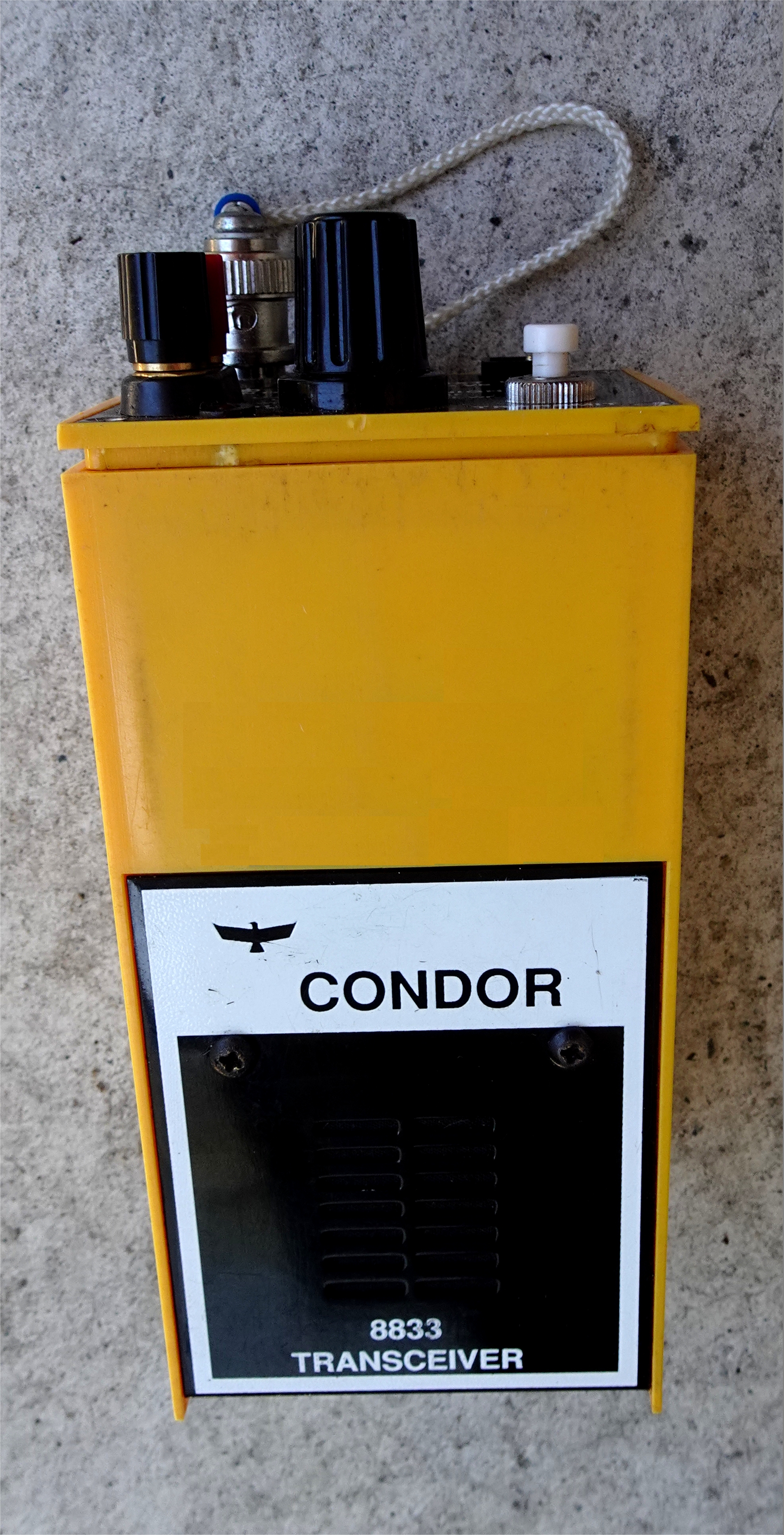
Figure 1 : The Condor HF SSB SAR handheld transceiver
(Note: Several versions of the Condor exist)
(Note: Several versions of the Condor exist)
Background
New Zealand is a country featuring many rugged and remote areas. Many of these beautiful unspoiled regions are within easy reach of most towns and cities, readily accessible for those keen to take advantage of these scenic spots. It should be no surprise that hunting, fishing, backpacking and mountain climbing are all popular pursuits in these areas for citizens and visitors to New Zealand.
Figure 2 : The Condor was designed for use in areas like this. Very similar places to this are just an hour or two's drive from my home. And really remote valleys that are even more amazingly beautiful are found about 30 minutes away... by helicopter.
Unfortunately, some of the people that visit places like this don't know what's needed in these remote, yet often easy to reach, places, even for a simple day-trip or picnic on a summer afternoon. They are often unfamiliar with these areas, the swift changes in climate that can occur in a matter of minutes, and the unexpectedly rough terrain. Folk routinely venture into these areas every year without telling anyone about their plans. They fail to take the right clothing, and often have no actual plan or destination in mind.
This can quickly lead to life threatening situations. And accidents happen to even the most experienced people. As a result, New Zealand has a highly experienced Search and Rescue (SAR) organisation. It draws on a well-proven mix of public safety staff and a large number of trained and experienced volunteers from a variety of community-based organisations. These include amateur radio operators, backpacking, skiing and mountaineering clubs.
The Development of SAR Radio Equipment
Radio
communications equipment has been critical for the small teams who
carry out these SAR operations. Over much of the past 80 years, HF
radio transceivers have been supplied to these search teams by the New
Zealand government. This is supported by an array of amateur radio
equipment owned and operated by trained amateur radio operators. In
addition, in recent years, equipment designed and built specifically
for the task by some specialist groups such as the backpacking, climbing, skiing and
mountain rescue clubs has also been extensively used. After WW2, inexpensive military surplus "ZC1" transceivers became popular with the hams manning SAR base operations, and similarly surplus "Number 27" sets for field use. The need to update this equipment during the 1960s led to the government-funded development of the portable TR-3 AM HF transceiver.
 These were in turn replaced in the early 80’s by the TR-105 5W SSB HF transceiver which is described briefly on my website here.
Both the older TR-3 (AM) and TR-105 SSB transceivers were two channel radios fitted with a
daytime 5 MHz and a nighttime 3 MHz channel.
These were in turn replaced in the early 80’s by the TR-105 5W SSB HF transceiver which is described briefly on my website here.
Both the older TR-3 (AM) and TR-105 SSB transceivers were two channel radios fitted with a
daytime 5 MHz and a nighttime 3 MHz channel.The compact dry-cell battery powered transceivers were supplied with a centre-loaded whip antenna, made from a series of slide-fit thin-wall metal tubes, and a lightweight rugged dipole.
Figure
3 : Here's an elderly TR-105 with its battery box (which is fitted as
the base of the transceiver) and handmade dipole antennas made to
replace the originally supplied and likely lost or damaged beyond
repair wire dipole antenna. There's no sign of the original TR-105 HF
centre-loaded whip antenna.
The Condor HF SSB Transceiver
Difficulties
with TR-105 spares and ongoing maintenance and a desire to reduce the
size and weight of equipment for the field search teams led to the
government-funded development of the Condor HF SSB transceiver. The
initial work was carried out by Dick Morris and C A Jenness at the Department of Scientific and
Industrial Research (DSIR) in Wellington. At the time, in the late 70’s, DSIR was actively studying the then emerging hybrid electronic module technology. A compact lightweight HF SSB SAR transceiver appeared to be an ideal target product for these hybrid modules. Hybrids were an important precursor to the later widespread development of surface mount technologies.

Figure
4 : The (blue) hybrid modules can be seen in this view of the
Condor transceiver. The plastic covered hybrid at
top-left is the three crystal oscillator hybrid module. It had to
remain free of the blue coating to allow crystals to be fitted. The
plastic cover prevented shorts to the shielding material sprayed
onto the inside of the case


Figure 5 : This original fixed tuned two-channel crystal oscillator hybrid module shows the typical internal structure with ICs and other bonded to the ceramic substrate. The miniature trimmer capacitors (top of LH photo) allow the crystals to be aligned precisely on frequency.
Hybrid modules were typically built on one or both sides of a thin rectangular ceramic wafer measuring from as little as 10mm square to as much as 30 x 40mm. Resistors could be screen-printed onto the ceramic wafers and laser-trimmed to very precise values if required.
Other components such as capacitors, inductors, trimmers and unpackaged ICs could also be bonded to the ceramic. Screen-printed conductors provided most of the connections, with manual or automated wire bonding used with ICs. One or more strips of IC-like pins were then bonded to the edges of the ceramic wafer prior to the entire assembly being encased in an tough epoxy coating. A number of these hybrids could be used in a product, for example by mounting them onto a simple “motherboard” PCB.
Hybrids can be very compact, robust and temperature stable. Their performance could also be much better than other approaches thanks to laser trimming. However, the cost of production was significantly higher than standard techniques. Any failures in service also usually required costly module replacement rather than replacement of a single faulty component. The (potentially) lower costs generated by higher volumes could offset these issues to some extent.
A basic 2-channel 1W PEP HF SSB transceiver using hybrids was designed by the DSIR team and described in a national electronics magazine in November 1981. Rather than using the traditional narrow-bandwidth filter method for transmitting and receiving SSB (See Appendix below), the DSIR design used the phasing SSB method. It was believed that the reduced size and weight possible with hybrid modules as well as their temperature stability, critical for satisfactory performance of a phasing SSB transceiver, made it the ideal approach.
Amazingly, and with enormous thanks to the kind generosity of Hugh Wilde ZL2BFB (Wellington Mountain Radio) and Eric Sears ZL2BMI, the transceiver which was the subject of that article has been preserved. (Figure 6)

Figure 6 : This is almost certainly the DSIR's original Condor prototype transceiver, constructed in a piece of plastic drainpipe and painted appropriately for the SAR service, and the unit probably submitted for type approval.
 Figure 7 : The prototype's (optional?) ceramic filter can be seen here along with the early unpackaged hybrids. The plastic insulation retained and insulate the modules from each other.
There were minimal differences between this and the production transceivers (Figure 1 and Figure 4).

Figure 8 : The antenna coupling toroid (red, lower left) does not include the later additional stacked filtering toroids. The (now rare) CA3020A output IC can be seen along with its flag heatsink.
A copy of a hand-written note from Dick Morris, one of the developers of the Condor, was kindly given to me by Eric ZL2BMI. This indicates Dick believed the CA3020A could operate at voltages above 12V. However, widespread use (and the IC maker's own datasheet) clearly and strongly demonstrated that using a supply voltage any higher than 12.0V would lead to device failure.

Figure 9 : This is likely one of the early production Condor transceivers with
the basic (Mountain Radio?) front panel. The Condor that I used for conversion
was a Police version. It used a more elaborate rotary switch for
channel selection and power.
As an aside, there is a third SSB method which is more popular today, a variation on the traditional audio and RF phasing scheme such as that used in the Condor. Proposed by Weaver in a seminal IRE paper published in 1957, it uses two separate audio phasing stages and a pair of sharp mid-band audio low pass filters. This avoids the need for hgihgly accurate wideband audio phasing networks but requires more elaborate audio filtering and precise I/Q channel matching. These latter issues are resolved with DSP implementations. (See the Appendix below for more details)
This "third method" was first used commercially by Redifon (UK) in the late 1950s and early 1960s before being largely ignored. It became popular again in more recent DSP-based SSB designs.

Figure 10 : Eight AA-cell batteries are inserted via a removable panel in the base. They occupy about 30% of the transceiver vlume. Did I mention it's very (very) tight inside that box?
Five hybrid modules were initially developed for the Condor by DSIR:
• Crystal Oscillator – 3 and 5MHz channel oscillators and a 455kHz quadrature oscillator
• Dual-gate MOSFET Amplifier/Mixer – RF and IF stages
• Phase Splitter Combiner – Audio quadrature module using all-pass op-amp filters
• Audio Processor – Rx AGC and audio preamp and Tx microphone amplifier stages
• Double Balanced Mixer – IC-based transmit mixers (DBM) for 455kHz - RF channel conversion
In total, eleven of these hybrids were used in the prototype transceiver along with a conventional LM386 speaker amplifier and a CA3020A RF 1W PEP linear amplifier on the main PCB.
The Production Version of the Condor Transceiver
The
production transceivers closely followed the original DSIR design and
were originally manufactured in the small rural town of Waihi in New
Zealand. Waihi is located at the southern end of the North Island’s
Coromandel Peninsula. Figure 1 shows the distinctive shape and colour
of the Condor transceiver. It was/is about the same size, shape, weight
and colour (bright yellow) of the (then) widely sold domestic New Zealand pack of butter. The original manufacturer is long gone from the scene. However, at some stage, production of the now rebranded Codan / Condor 8833 was shifted to Wanganui, another small North Island town. In total, 300 of these transceivers were manufactured for New Zealand’s Search and Rescue organization, a further 100 were sold to the Mountain Radio Service, and some sources estimate that some (50?) were sold to other customers.
The cost of the transceiver has not been able to be verified. A price of about $NZ2,200 was suggested by Bob Sewell ZL2ASO (SK). Bob worked at DSIR and knew Dick Morris well. Since Bob was actively involved with Wellington's Mountain Radio Service, it's possible this price was for the MRS Condor radios. The SAR contract price may have been different. The SAR radio price probably reflected the total value of the contract (including setup, transceivers, manuals, spares, and antennas) divided by the number of radios supplied.
By any measure, the Condor was likely a relatively expensive transceiver. It reflected the technology and the manufacturing challenges. To give a better idea, the price of a mid-performance commercial 100W ham radio HF SSB transceiver at the time, such as the Yaesu FT-101 or Kenwood TS-520, was about $NZ600.
Of course, neither of these transceivers could operate from a set of AA batteries and be carried around the New Zealand bush for days in a backpacker’s pack!

Figure
11 : The side view of the unmodified Condor shows the dual double
balanced mixer hybrid used in the transmitter and the plastic cover on
the original crystal oscillator module.
The Condor’s features included:
• Two fixed crystal controlled channels in the 1.6 – 6MHz band
• SSB (A3J) with selectable USB or LSB modes on some versions
• Rx sensitivity: Better than 2.5uV 12dB SINAD (Sample measured 0.35uV for 10dB S/N)
• 55 dB adjacent channel rejection
• Tx: 1W PEP output
• 40dB carrier attenuation (45dB measured)
• 40dB opposite sideband attenuation (55dB measured)
• 12V (8 x AA-cell) internal supply, 9 – 12V (MAX!), optional external 12VDC power
• Rx: 30mA Tx: 180mA
• 160 x 57 x 55 mm (Transceiver only)
• 510 gm
The user’s front panel controls included:
• Channel selection combined with mode selection on some versions
• Power switch
• PTT pushbutton
• Battery low LED
Operational Use
Ultimately,
the Condor proved to be a challenging radio to keep in service. The
hybrid modules had a habit of bouncing out of their SIL sockets with
bumps and vibration in the field. These were then “gunked” into place
with RTV, a soft silicone rubber compound, making later maintenance
slightly more difficult but largely resolving the problem. Faulty
hybrids, however, could only be repaired by replacement. Spare hybrids
became increasingly expensive during the in-service life of the
transceiver, and ultimately they became unobtainable. The CA3020A IC used in the transmitter final linear amplifier also became increasingly difficult to obtain at reasonable prices. Originally designed and made by RCA in early 1967 and manufactured in the mid-80s under their Intersil brand, manufacture passed to Harris in 1988 when RCA/Intersil was sold. Harris appears to have halted sales of the CA3020A around 1995 although it remained available until 2002-3. A few devices can still be found but they can be costly. A set of five could be purchased for $US815 plus freight in mid-2023.
The absolute maximum supply voltage for the CA3020A is 12V. In service, it was all too easy for that voltage to be exceeded in service, typically by someone accidentally plugging the radio across a vehicle battery (i.e. into 13.8V). This issue was not helped by the ‘centre-pin negative’ polarity of the front panel DC supply socket!! Curiously, the prototype does not have this arrangement. Instead, it used a centre-positive socket and had additional wiring, via a polarity switch, allowing for battery jumper power leads
All of these issues, added to the modest 1W output power of the radio, ultimately led to the radio’s removal from SAR service in New Zealand during the mid-90s, being replaced by the Polsar SR-3 5W handheld SSB transceiver. The Polsar was based on the successful Mountain Rescue Service’s MRS-1, MRS-2 and MRS-3 5W SSB dual channel HF transceiver family. Also designed and made in New Zealand, these rugged and reliable portable transceivers will hopefully also be described here in the near future.
The MRS Condor sets were withdrawn from much of New Zealand, some as recently as early 2023. However, the Condor is still in use (late 2023) in the two North Island groups that are still operating. They are very much favoured by backpackers and climbers over the SR3 which is considerably heavier. As many as 20 or more may still be operational with the Wellington and Hawkes Bay Mountain Radio Services.
The Condor transceiver must surely represent one of the most interesting examples of the use of New Zealand taxpayer dollars!
Technical Overview of the Condor Transceiver
The
production Condor transceiver closely followed the original DSIR
design. Figure 12 shows the block diagram of the Condor transceiver.
Figure 12 : Block diagram of the Condor phasing SSB handheld transceiver
The full circuit diagram (PDF) is available in the Download section for those interested in the detail.
The receive signal from the antenna passes through a broadband matching transformer, the secondary side being paralleled by one of two selectable resonant circuits for each of the two transceiver channels. These provided some broad receiver filtering but appears primarily aimed at transmitter third harmonic filtering. It typically adding 20 to 30dB attenuation depending on the frequency.
The receive signal goes on to the first RF amplifier and then to a two pairs of resonant circuits, one pair per channel. These provide the bulk of the channel filtering, vital in a radio using a low 455kHz IF. The signal then proceeds to the first mixer which converted the signal to 455kHz. A ceramic IF filter was optionally fitted here. It significantly improves the adjacent channel selectivity. It is replaced by a small 22p ceramic capacitor when the filter is omitted.
The IF signal goes to the detector where a pair of balanced mixers are fed with two 90o phase shifted 455kHz carriers generated from a crystal oscillator at 1820kHz and ‘divide by 4’ flip-flops. The I and Q audio outputs then pass through the 90o phase shift audio stage. The result is the selection of the wanted sideband and the cancellation of the unwanted sideband. In the production Condor tested (without ceramic filter), the unwanted sideband was attenuated by at least 45dB.
The audio is amplified in the audio hybrid stage for the handheld’s speaker. This hybrid also produces the AGC voltage for the RF amplifier and first mixer. It varies between 3V (-60dBm i.e. strong signal) and 8V (-120dBm i.e. weak signal) and is superbly linear across this 60dB dynamic range of the over 90dB gain range of the receiver chain.
The transmitter operates in a similar manner but in the opposite direction. The microphone audio, using the speaker, is amplified and compressed when required, and passes through the audio phase shifter to generate I and Q audio inputs for the dual balanced mixer. This results in a 455kHz SSB signal which is mixed with one of the two carrier oscillator signals in the transmit mixer and passed through the selected bandpass filter. This signal is amplified in the final RF amplifier stage to produce the 1W PEP transmitter output.
DSIR credited the audio phase shifter design to a design note published by R Dickey from Cal Polytech. This circuit was considered ideal for the laser trimmed hybrid technology planned for the Condor.
For production, two further hybrids were added to the original set of five DSIR-designed modules – an RF Switch module which appears to use one or more CD4066 or CD4053 CMOS switches, and a Dual Double Balanced Mixer hybrid which combined two of the DSIR single DBM hybrids (probably using MC1496 or TCA820 chips with laser trimmed balance resistors) on a single hybrid, most likely to reduce cost or space. This gave an available set of seven different hybrids but reduced the total number of hybrid modules required in the transceiver from eleven to nine.
Note: To date, no schematics for these two modules have been located. I can guess....but it would be nice to know the actual details.
The speaker amplifier was redesigned to integrate the LM386 functionality, and improvements were made to the transmitter output filtering to reduce spurious and harmonic emissions.
There are a number of unusual features in the Condor’s design aside from its use of the SSB phasing method and hybrid technology. The first is the output coupler from the 1W transmitter power amplifier (CA3020A). In addition to the usual wideband toroid transformer used to match the PA’s 400 ohm output with the 75 ohm (!) antenna, the output coupler and filter assembly included a channel-selected toroidal bandpass filter paralleled with the transformer secondary.
Interestingly, the two filter toroids were mounted concentrically with the output coupler toroid(!). This saved considerable PCB space. As noted earlier, these improve the harmonic and spurious output performance of the transmitter.

Figure 13 : The transmitter PA, using an “unobtainium” CA3020A, is fitted with the heatsink seen at lower centre. This is connected to two concentrically-mounted toroids and a third output coupler toroid stacked vertically (!) to the left of the heatsink.
There is a further pair of coupled shielded LC tuned circuits, one pair per channel. These are switched between the transmitter and receiver. (These can be seen to the right of the heatsink in Figure 13) These filters follow the receiver RF front end (hybrid) amplifier stage in receive and after the (455kHz IF to RF channel) transmit-side mixer just prior to the transmitter RF PA stage. The filter switching required for this with the two channel production radio probably led to the development of the additional RF Switch hybrid in the Condor which was not present in the original published design.
Modifying the Condor for Amateur Radio
A
number of decommissioned Condor transceivers were made available to my
local amateur radio club for SAR training and for QRP (low power)
amateur radio use. Sensibly, regulations prevent the Condor’s use for
amateur radio on the official 3MHz and 5MHz SAR channels. This
required the replacement of these crystals but this is very expensive
and highly undesirable. Consequently, I developed a special version of my SugarCube-Plus digital VFO board for the Condor. In addition, I modified the Condor for operation on 80m and 40m, carried out the mechanical changes required to add the OLED display to the front panel, and tested the modified transceiver to ensure it was operating in compliance with regulatory requirements.
In addition, since the transceiver is designed for 75 ohms, a suitable antenna is required for portable use. That demanded the design of a suitable compact SWR meter for 75 ohms, and a suitable antenna tuner to allow a range of antennas to be used in the field.
And, since the Condor VFO is constructed using SMD parts, except for the ATtiny85 to ease reprogramming, a side project involving the design of SMD assembly systems was undertaken.
Modifying the Condor has been a lengthy journey for me, but ultimately, very rewarding when I can operate the modified Condor transceiver today some four decades after first seeing it. I had gone to visit Dick Morris to see this new Condor radio and the hybrids used to build it. I was a young professional radio engineer responsible at the time for providing engineering support for the maintenance of the TR-105 HF SAR radio equipment in New Zealand.
Well, these topics will be the subject of the next series of web-pages to be uploaded very shortly. To whet your appetite a little, the features of the modified Condor transceiver for amateur radio currently include:
• 3.50 – 3.75MHz (80m) and 7.00 – 7.30MHz (40m) continuous coverage
• User programmable high and low band limits and start-up frequencies on each band
• User selectable VFO tuning rates – 10 and 100Hz, 1 and 10kHz steps
• SSB (A3J) with automatic USB (60m) and LSB (80m) mode selection
(Required if 60m is used instead of either 80m or 40m)
• Rx sensitivity: Better than 2.5uV 12dB SINAD (Measured 0.35uV for 10dB S/N)
• 45 dB adjacent channel rejection (55dB with optional ceramic filter)
• Tx: 1W PEP output
• 40dB carrier attenuation (45dB measured)
• 40dB opposite sideband attenuation (55dB measured)
• 12V (8 x AA-cell) internal supply, 9 – 12V (MAX!), optional external 12VDC power
• Rx: 60mA Tx: 180mA
• 160 x 57 x 55 mm
• 520 gm
User Panel Controls:
• 64 x 32 pixel OLED display
• Full digital frequency display with 10Hz resolution i.e. 3.68453 MHz
• OLED tuning step indicator shows selected tuning rate
• S-meter bar-graph display (Linear from -110dBm to -60dBm / S0 to S9+20dB)
• 9-12V OLED expanded battery level meter (on OLED display)
• Power switch
• Band switch
• PTT pushbutton
• Tuning lock button (Lock mode status icon appears on the OLED)

The Next Step(s):
Click on the linked text to reach the next part(s) in the Condor transceiver series...
Part 2: Building the SC+C SugarCube-Plus VFO for the Condor Transceiver
Coming Shortly:
Part 3: Converting the Condor SAR Transceiver to 80m/40m Amateur Radio OperationPart 4: QRP Antenna Tuner(s) for the 80m/40m Condor TransceiverPart 5: Test Equipment accessories for the Condor transceiverPart 6: Condor Transceiver FAQsPart 7: Obtaining a Kit (and a transceiver) for the Condor ConversionIf I feel really brave in the near future, I may add:
Part 8: Operating CW and FT-8 (and other digital modes) on the Condor transceiverThanks
Considerable
time-consuming and exhaustive research, especially over the past two years,has been spent looking into the Condor radio and
the design of the modifications and the related accessories described
on this website. This work is continuing with other ex-SAR radios here in New Zealand including the TR-105.Valuable assistance and advice (and some of the items pictured here!) have been kindly and generously provided from a number of individuals and organisations. These are probably far too numerous to name here, there are a few who I've been asked not to name, and this held has all been very much appreciated.
In particular, my sincere thanks go out to a number of individuals and organisations in New Zealand including (and in no particular order):
- Ian MacPherson, Richard Smart, Keith Birse ZL4JA, and David Howe (NZART Christchurch Branch 05)
- Eric Sears ZL2BMI and Hugh Wilde ZL2BDB
- NZ Police technical staff and archivist
- Archives NZ and the NZ National Library, and
- Ian Gardiner (Mountain Radio Service) and Neil Lambert (Wellington)
Appendix:
What is SSB and how is it generated?
Or: Why is the Condor transceiver so very special?

Figure 15 : Amplitude modulating a radio carrier with
a single tone results in a signal with two equal
sidebands, one above and one below the carrier.
a single tone results in a signal with two equal
sidebands, one above and one below the carrier.
An AM signal (Figure 15) contains a carrier at a specific frequency, say 1MHz for a AM broadcast transmitter, along with two sidebands. These vary in level according to the level of the voice at each frequency, and are spaced from the carrier equal to the voice frequency at that moment. Voice frequencies have most energy from 300Hz to, say, 4kHz. The transmitted signal contains equal information in both Lower and Upper sidebands (LSB and USB). The AM signal, with its carrier, LSB and USB requires a bandwidth of at least 8 kHz. Since no transmit signal is perfect, and receiver tuning and filtering is similarly imprecise, and allowing for some drift in the carrier frequency (especially in the early days of radio), the channel used for this AM signal might be, say, 10kHz wide.
Since an RF carrier contains no voice modulation, and since one sideband contains the same information as the other, it is possible to just transmit a single
 sideband (SSB), reduce the required bandwidth to, say, 5kHz, and still
be able to send and receive the same signal. Overall, actually, this
can save lots of power and improve the signal quality by some 9dB.
sideband (SSB), reduce the required bandwidth to, say, 5kHz, and still
be able to send and receive the same signal. Overall, actually, this
can save lots of power and improve the signal quality by some 9dB.Figure 16 : Amplitude modulated carrier showing identical sidebands
To create an SSB signal, we must remove the carrier and one sideband from the original AM signal. A balanced modulator, a mixer which mixes/modulates the carrier with the voice signal, can produce a double sideband (DSB) signal containing both USB and LSB signals while removing the carrier. Eric ZL2BMI's DSB transceiver in Figure 17 is an excellent example of this.

Figure 17 : ZL2BMI's tiny DSB transceiver
There are three ways to remove the unnecesary sideband: A very narrow bandpass filter can select the wanted sideband and reject the nearby unwanted sideband. This is the basis of the filtering method. Alternately, if the carrier and audio signals are each generated directly (i.e. Without any phase shift, "in-phase" or "I" signal) and as a "quadrature phase shifted" ("Q") signal, these can be subsequently mixed together in several balanced modulators to ensure both carrier and unwanted sideband (either LSB or USB) are rejected. This is the phasing method.
This approach requires an accurate 90-degree audio phase shift from at least 300Hz to 3kHz. That's traditionally very difficult to do, especially where temperatures vary dramatically i.e. In the bush and up mountains. That's one reason why the Condor transceiver which uses this method is so very special. SAR radios reverted to the easier filter method in subsequent equipment.
These days, it's much easier to use digital signal processing (DSP) to generate and detect stable SSB using the software equivalent of the Condor's phasing SSB analog circuits of 1980. it would be two decades before phasing method SSB (in DSP form) would arrive in a desktop-style ham HF SSB transceiver (Figure 18), and four decades for DSP software in a microprocessor would permit phasing SSB to be used again in radio amateur circles in a similar portable package (Figure 19).
I think that all of thismakes the Condor SAR transceiver very important here in New Zealand, and a transceiver that's really worth a lot of my time and effort restoring and converting carefully for amateur radio use once again.

Figure 18 : Commercial amateur radio transceiver with TMS320 DSP processor
for generating and receiving SSB modulation (Image courtesy of Icom Japan)
Figure 19 : The (tr)uSDX portable transceiver is the result of colaboration between
PE1NNZ and DL2MAN. It uses a modern Microchip/Atmel ATmega328 and DSP
algorithms in firmware to generate and detect SSB in 5 bands across the HF spectrum.
Downloads
Circuit diagram of unmodified Condor SAR Transceiver (JPG)
Want to go back to the main page? Click here to return directly.